Technical Briefing: Systematic 12V Circuit Diagnostics
- May 29, 2026
- 866
- DAIER Technical Team
In professional automotive and marine applications, electrical system downtime is a direct threat to operational efficiency and brand reputation. Identifying the root cause of a circuit failure requires more than anecdotal evidence; it demands a standardized engineering approach. This technical briefing outlines a professional diagnostic pathway to identify high resistance, manage inductive surges, and verify ground plane integrity using quantitative measurement protocols.
Source Potential Analysis: Beyond Resting Voltage
Reliability begins at the source. A common failure in field diagnostics is the over-reliance on “resting voltage” as a metric for battery health.
- Potential vs. Capacity: A lead-acid or LiFePO4 battery may display a nominal resting voltage (12.6V – 13.2V) yet fail instantaneously under a high-amp load. This is often due to increased internal resistance or a degraded cell.
- The Dynamic Load Test: Diagnostic protocols must include measuring voltage at the battery terminals during a high-current event (such as a winch engagement or engine crank). If the potential drops below 10.5V during this event, the battery is technically compromised, regardless of its resting state.

Circuit Integrity: Primary and Secondary Protection Metrics
When the power source is verified, the diagnostic focus shifts to the circuit’s “gatekeepers.” In professional builds, protection is tiered between primary (Master Breakers) and secondary (Branch Fuses).
- Continuity is Not Enough: A simple continuity “beep” confirms a physical path but does not confirm the path’s ability to carry current. A fuse with a partial hairline fracture may show continuity but will fail under the thermal load of actual operation.
- The Advantage of Manual Reset Breakers: For B2B applications and heavy-duty machinery, Manual Reset Circuit Breakers are preferred over fuses. They provide a repeatable mechanical disconnect and immediate visual confirmation of a tripped state. If a breaker trips immediately upon reset, it indicates a “Dead Short”—a direct positive-to-negative or positive-to-chassis contact that must be cleared before the system is re-energized.
Internal Link: For high-amperage applications, understanding the trip curve is essential. Refer to the Fuses vs. Circuit Breakers Comparison for engineering specifications.
Switching Architecture: Managing Inductive Loads and Arcing
Mechanical switches and relays are the primary points of failure in high-cycle environments.
- Switch Contact Degradation: In circuits driving motors or pumps, the “inductive kickback” upon de-activation can cause internal arcing. This leads to carbon buildup (pitting) on the contacts, increasing resistance.
- The Relay Solution: To preserve the life of dashboard switchgear, Automotive-Grade Relays must be integrated to handle the high-current load.
- Diagnostic Tip: If a relay “clicks” but no power reaches the load, the low-current trigger circuit is functional, but the high-current internal contacts have reached their end-of-life cycle.
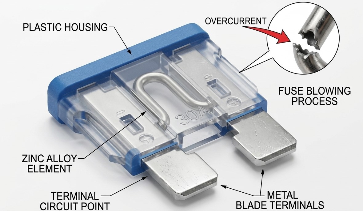
The Physics of Resistance: The Voltage Drop Test
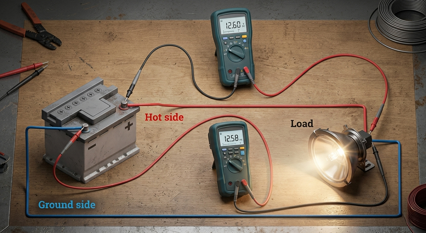
The most sophisticated diagnostic tool in an engineer’s arsenal is the Voltage Drop Test. This test identifies “hidden” resistance that a standard voltage check cannot detect.
- The Problem of Resistance (R): Corroded terminals, loose crimps, or undersized wire gauges act as a bottleneck. According to Joule’s Law (P=I²R), this resistance creates heat, further degrading the connection in a destructive feedback loop.
- Executing the Test: The test is performed with the circuit active. By measuring the potential difference between two points on the same wire (e.g., from the battery positive to the device positive), the multimeter reveals how much energy is being lost to heat.
- The Threshold: In a professional 12V system, a voltage drop exceeding 0.5V across a single run indicates a failed connection or an improperly spec’d wire gauge.
Accurate wire sizing is the first defense against voltage drop. Consult the AWG Wire Gauge & Length Guide for standardized sizing charts.
Ground Plane Integrity: Solving the “Ghost Ground”
In the automotive and marine industries, the negative (ground) side of the circuit is responsible for approximately 80% of intermittent electrical failures.
- Chassis Ground vs. Common Bus Bar: While a metal chassis can serve as a ground in automotive applications, it is prone to rust and paint interference. In marine applications, a dedicated Ground Bus Bar is mandatory to prevent galvanic corrosion.
- Common Impedance Coupling: A weak ground can cause power to “back-feed” through other devices, leading to strange symptoms like dimming lights when a pump is activated.
- Remediation: All grounding points should be cleaned to bare metal and protected with dielectric grease to prevent atmospheric oxidation.
Load Testing: Final Verification
If the circuit verifies 12.6V at the load terminal with zero voltage drop and perfect ground integrity, but the device remains inoperative, the internal failure lies within the device (the “Load”) itself.
- Bench Testing: Isolate the device and apply direct 12V power from a known-good source. If the motor fails to spin or the LED fails to illuminate, the component is an “Electrical Anchor” and must be replaced.
Conclusion: Systematic Reliability
Electrical troubleshooting in professional environments is a matter of logic, not luck. By following a structured pathway—verifying source potential, testing protection, managing switching loads, and eliminating voltage drop—technicians can minimize MTTR (Mean Time to Repair) and ensure long-term system stability.
Daier provides the technical backbone for these reliable systems. From Heavy-Duty Switches to precision Fuse Blocks, every component is engineered to withstand the stressors of professional use.
Strategic Partnering: For wholesale procurement, custom OEM solutions, or technical data sheets, contact the Daier engineering team today.
