Power Distribution Block Selection Guide for Low Voltage DC Systems
- October 14, 2026
- 33
- DAIER Technical Team
A power distribution block provides a common connection point for a main supply cable and several branch circuits. A suitable layout reduces unnecessary cable runs and makes connections easier to inspect. Selection depends on the maximum system voltage, continuous current, terminal arrangement, cable and lug dimensions, and installation environment. This guide covers battery and accessory distribution in automotive, marine and RV equipment, with examples from the DAIER busbar and power distribution block range.
1. What a Power Distribution Block Does in a DC Circuit
One Input to Multiple Outputs Explained
A common distribution block connects several conductors through one conductive plate or junction. The main connection and shared conductive path must accommodate the combined current of the connected loads under the intended operating conditions. Each branch connection also has its own limits. Check the stated continuous rating, any separate terminal ratings, and the manufacturer’s installation requirements. A total assembly rating must not be assumed to apply to every screw terminal or stud individually.
Distribution Block Compared with a Bus Bar and a Terminal Block
Busbars and power distribution blocks overlap in function. A busbar usually provides a common conductive bar with several connection points; a distribution block often places those connections in a compact insulated assembly. Both may use studs, screws or cable clamps. Terminal blocks can provide separate connections or linked circuits and are available for control wiring as well as higher-current power wiring. Select by the electrical arrangement and documented ratings rather than by the product name alone.
| Component | Connection arrangement | Protection | Selection focus |
|---|---|---|---|
| Distribution block | Common junction or separate paths | Usually external | Input and branch limits and cable fit |
| Busbar | Shared conductive bar or independent bars | Usually external | Continuous current and circuit arrangement |
| Fuse block | Distribution through fuse positions | With compatible fuses fitted | Total and branch ratings and fuse suitability |
| Terminal block | Separate or linked terminals | Usually external | Conductor range and voltage and current ratings |
Where the Block Sits in the Power Path
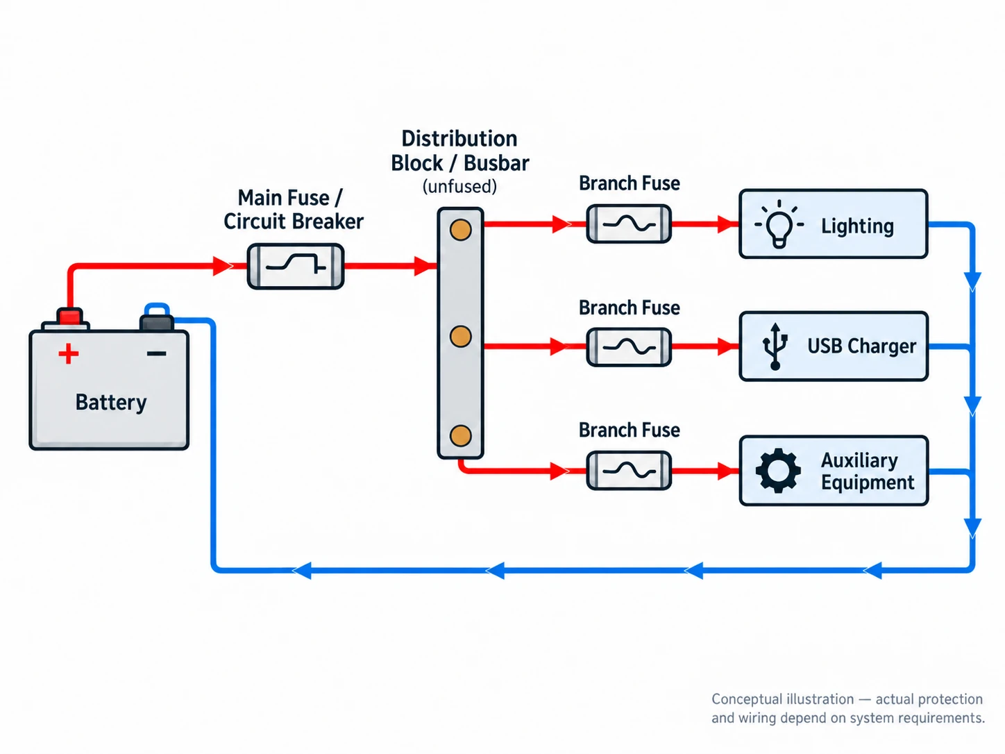
In a typical battery accessory circuit, the main positive feed has overcurrent protection near the source, followed by a distribution point and protected branch circuits. A fused distribution assembly can combine the distribution point and branch protection. Place branch protection at the appropriate point where a smaller conductor begins, in accordance with the equipment instructions and applicable installation requirements. A disconnect switch provides isolation but does not replace a fuse or circuit breaker. The exact sequence depends on the system design.
2. Choosing the Right Current Rating and Stud Size
Comparing Continuous Current and Terminal Layouts
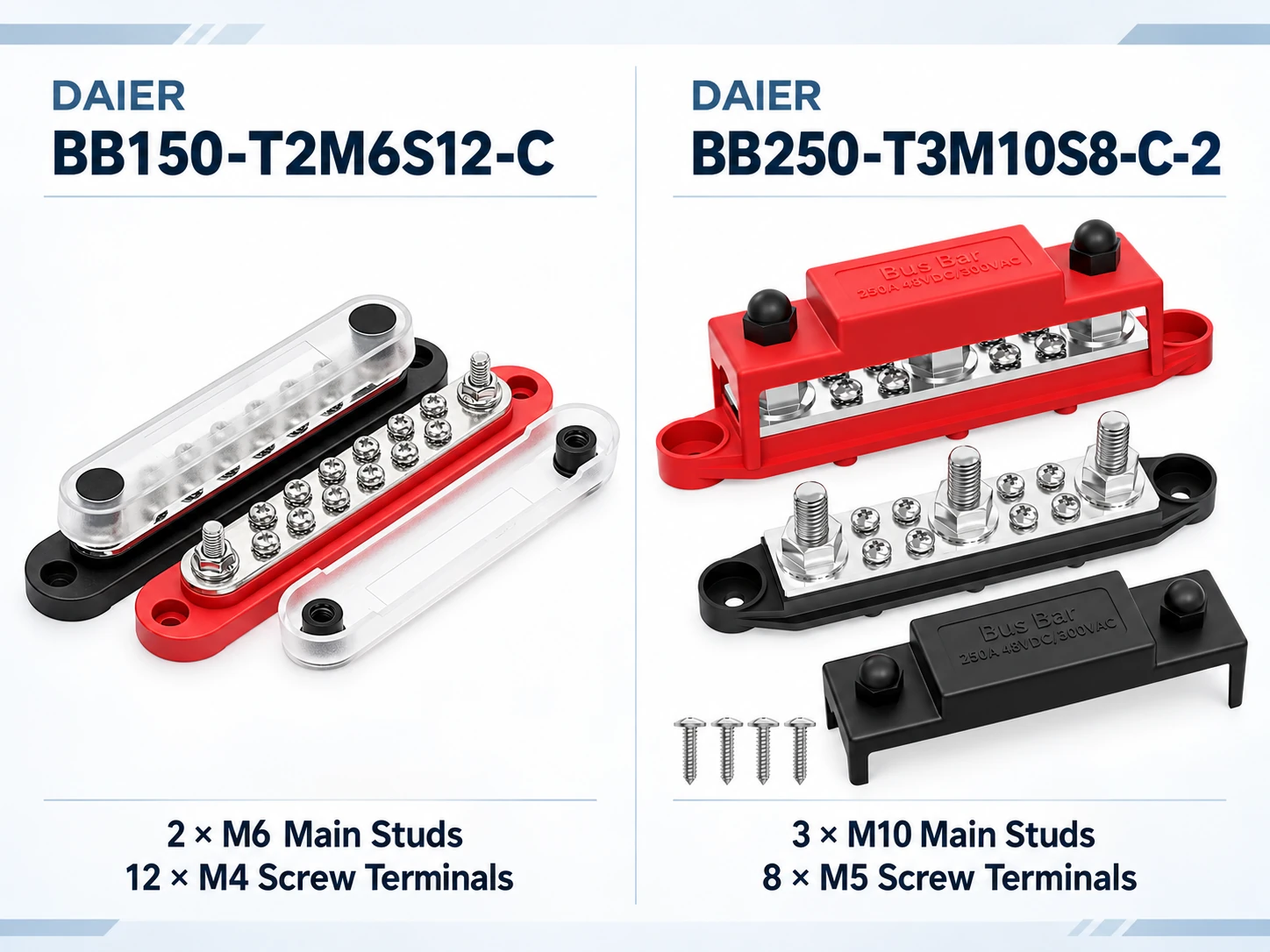
Calculate the expected simultaneous load, then check the continuous rating and installation conditions of the proposed assembly. The BB150-T2M6S12-C is listed as a 150A busbar with two M6 studs and twelve M4 screws. The BB250-T3M10S8-C-2 provides three M10 studs and eight M5 screws; its product data lists a 250A continuous rating at 12V and a maximum voltage of 48V DC.
These examples illustrate different connection layouts. Confirm the approved operating conditions and individual terminal limits for the actual project rather than treating a voltage range as a guarantee of identical performance in every installation.
Matching Studs to Cable Lugs
Select the cable cross-section for the load, circuit length, allowable voltage drop and installation conditions. Then select a compatible lug barrel for that conductor and a lug hole that fits the specified stud. M6, M8 and M10 identify metric stud sizes; approximate inch equivalents in a catalog are not a substitute for checking the lug manufacturer’s dimensions. Stud diameter alone does not establish the supported AWG range or allowable current. Check lug width, stacking limits, cover clearance and tightening torque before ordering.
Checking Input and Branch Cable Connections
For a cable-clamp distribution block, verify the supported conductor range, conductor type, strip length and tightening instructions for every input and output. For a stud assembly, check the lug dimensions and permitted terminal arrangement. A conductor-size range is a mechanical compatibility specification, not an ampere rating. Neither the input cable size nor the number of outputs removes the need to calculate load and check the rating of each connection.
3. Fused and Unfused Distribution Blocks
When a Fuse Block Makes More Sense
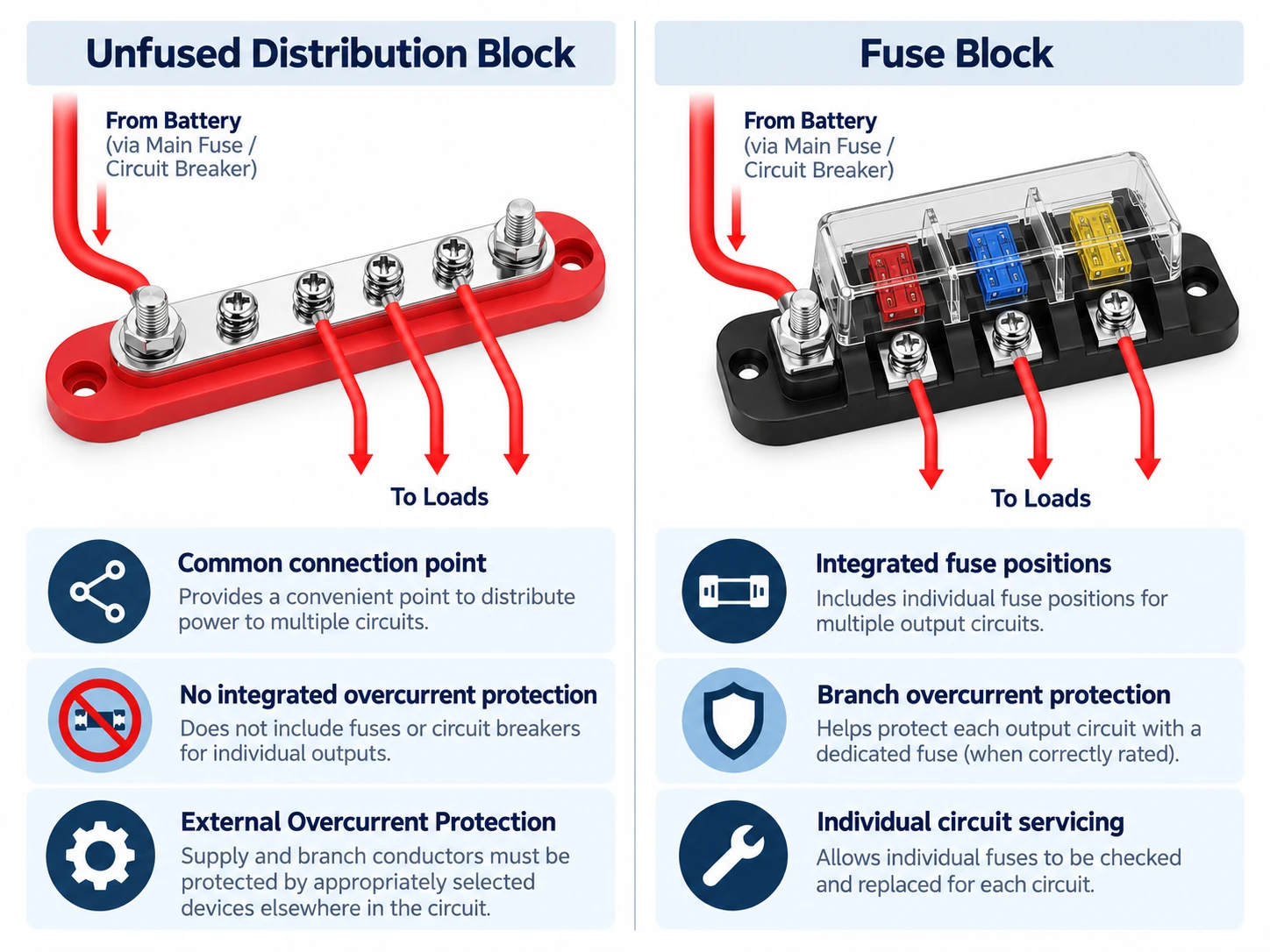
An unfused block provides a connection point without overcurrent protection. Protection for the connected conductors must be provided elsewhere in the circuit. A fuse block integrates fuse positions and can simplify branch-circuit servicing. Check the compatible fuse format, maximum DC voltage, total assembly current and individual circuit ratings. DAIER’s Fuse Blocks and Holders category provides related options when the project requires protected distribution rather than a common unfused junction.
ANL and High-Current Fuse Distribution Kits
ANL and other high-current fuse formats may suit larger battery loads, but the format alone does not establish suitability. Check the fuse’s rated current, time-current characteristic, maximum DC voltage and interrupt rating against the load and available fault current. Also check the holder and connection ratings separately. Normal load current and short-circuit interrupt capacity describe different requirements. For a fused kit, confirm the wiring diagram, usable circuit count and included fuse configuration before specifying it.
Protecting the Input Feed
Size main protection to protect the supply conductor while accommodating the intended load and its starting behaviour. Also verify the protective device’s DC voltage rating and interrupt capacity. Locate the device close to the source as required by the installation design, limiting the length of unprotected cable. With a battery-to-fuse-to-switch arrangement, opening the switch leaves the fuse and its battery-side wiring energized. Identify the live sections and follow the equipment’s isolation procedure before servicing.
4. Ground Distribution and Dual-Row Layouts
Negative Ground Bus Configurations
A negative bus provides a common return connection for the intended circuits. Size the shared return path for the current it must carry and inspect its connections for heating or corrosion. A DC negative connection is not automatically the same as chassis bonding or protective earth. The approved system diagram determines whether and where those paths connect. Follow the specified return arrangement rather than introducing additional connections to the chassis or engine block.
Dual-Row and Multi-Stud Layouts
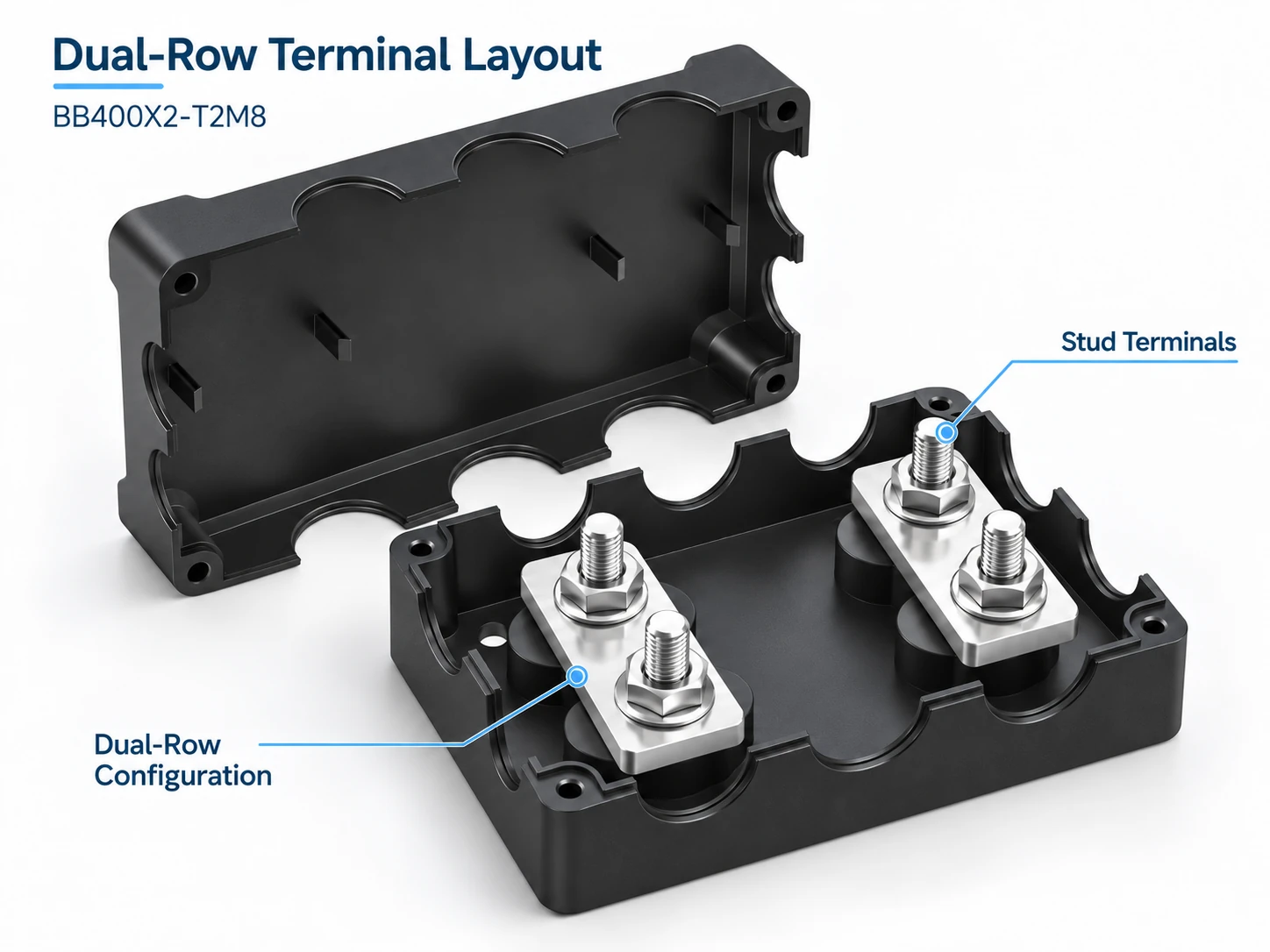
Two studs can share one conductive bar, so stud count does not demonstrate electrical isolation. A dual assembly may contain independent positive and negative bars, but the internal arrangement must be confirmed from the wiring diagram. The BB400X2-T2M8 product page lists four M8 studs, a maximum voltage of 48V DC and a 400A continuous rating; confirm the connection diagram and whether the rating applies per bar or to the assembly before specifying separate feeds. The public rating does not establish that each row can independently carry 400A.
For a simple common junction, the BB1-1 single-stud series offers M6, M8 or M10 options with variant-dependent ratings. Confirm the exact variant and permitted lug stack.
5. Applications by Vehicle and Environment
Marine and Boat Installations
Marine installations require attention to moisture, corrosion, vibration and access for maintenance. Select conductor materials and surface finishes appropriate to the installation, and verify any claimed ingress protection for the specific assembly and cable entries. A protective cover helps prevent accidental contact but does not by itself establish waterproofing, salt-spray resistance or ignition protection. Locate the block in an appropriate protected space and provide strain relief for the connected cables.
Automotive Audio and Auxiliary Circuits
A vehicle accessory layout often uses one protected supply cable to a distribution point near the loads, followed by individually protected branches for lighting, charging outlets or other equipment. This can simplify routing, but each branch still needs a conductor and connection suitable for its load. Allow space for cable bends, lug access and the cover. For amplifier and motor circuits, account for starting or transient demand when selecting conductors and protective devices.
Battery-Side Distribution in Solar and Higher-Voltage Systems
For a solar-powered installation, distinguish the battery-side distribution circuit from the PV array circuit. A component marked 48V DC maximum must be checked against the battery’s highest charging voltage and the equipment requirements; a nominal 48V battery system may exceed that limit. PV string voltage can also be substantially higher than battery voltage, particularly under cold open-circuit conditions. Do not specify a low-voltage battery distribution block as a PV combiner merely because the installation includes solar panels. Array-side components require their own voltage, current and protection assessment.
6. Installation Practice That Prevents Failures
Torque, Contact Area and Plating
Use the manufacturer’s specified tightening torque and assembly order with suitable tools. Loose connections can increase resistance and heating; excessive torque can damage the stud, lug or housing. Cable lugs should make the intended conductive contact without insulating material or incorrectly placed washers between the mating surfaces. Follow the approved lug-stacking and washer arrangement. Prepare and terminate conductors using the specified lug and crimp tooling, and do not remove protective plating by sanding or filing.
Insulation, Covers and Clearance
Fit covers intended for the assembly and maintain the clearances specified for cable entry, lug placement and servicing. Support cables so vibration and cable weight do not load the terminals, and protect routing from sharp edges and heat. Clearance must be based on the equipment dimensions and installation requirements, not a general finger-width rule. Before commissioning, verify circuit identification, connection arrangement, protection and tightening against the approved design.
7. Sourcing Distribution Blocks and Bus Bars
DAIER offers busbars and power distribution blocks in common-junction, multi-terminal and dual layouts for low-voltage DC projects. Compare models in the Busbar and Power Distribution Block category, then confirm the exact variant, voltage limit, continuous rating, terminal dimensions and cover requirements. For a catalog or OEM enquiry, send the following details through the contact page:
- Part number or drawing and maximum operating voltage
- Continuous load and branch quantity
- Cable and lug dimensions and available mounting space
- Expected order quantity
These details support review of a suitable connection layout without assuming that one model covers every application.
