What Is a Rocker Switch? Types, Wiring, and Selection Guide for Engineers
- August 14, 2026
- 348
- DAIER Technical Team
A rocker switch is an electromechanical switch in which an actuator rocks back and forth around a central pivot point to open or close an electrical circuit. Whether you are designing industrial machinery, automotive panels, or marine controls, this comprehensive rocker switch guide covers internal mechanics, pinout wiring diagrams, electrical ratings, and engineering selection criteria.Because of their intuitive operation, high current handling capabilities, clear visual state indication, and ease of panel mounting, rocker switches are standard components across industrial machinery, marine systems, automotive controls, commercial appliances, and power distribution units (PDUs).
For design engineers and purchasing managers, selecting the right rocker switch requires more than matching physical dimensions. It demands an understanding of contact mechanisms, circuit topologies, electrical load dynamics, ingress protection (IP) ratings, and mounting configurations.
This guide provides a comprehensive technical overview of rocker switches, including internal mechanics, pinout configurations, selection parameters, and wiring logic.
1. Internal Mechanics: How a Rocker Switch Works
Understanding the internal construction of a rocker switch helps engineers evaluate mechanical durability, electrical life, and performance under high-inrush current loads.
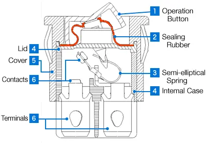
Core Internal Components:
- Actuator (Rocker): The external lever pressed by the operator. Typically molded from flame-retardant polyamide (Nylon 66 / PA66) or polycarbonate (PC).
- Plunger & Spring Mechanism: Located beneath the actuator. When the rocker is pressed, it compresses a spring-loaded plunger, forcing it to slide across an internal pivot bridge. This creates a tactile snap action and moves the internal contact arm.
- Movable Contact (Armature): A conductive metal bridge (typically copper alloy or phosphor bronze) that tilts or slides to bridge stationary contacts.
- Stationary Contacts & Terminals: Fixed electrical connection points protruding from the switch housing.
- Contact Material: High-quality industrial rocker switches utilize Silver Alloy contacts (such as Silver Tin Oxide, AgSnO2, or Silver Cadmium Oxide, AgCdO) to resist arc erosion, contact welding, and oxidation under heavy loads. Gold-plated contacts are reserved for low-voltage, low-current signal switching.
2. Rocker Switch Types: SPST, SPDT, DPST and DPDT Explained
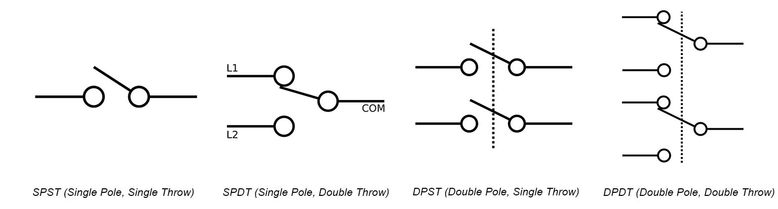
Rocker switches are categorized by their contact configurations (Poles and Throws) and actuation behavior (Latching vs. Momentary).
Pole and Throw Configurations
A. Single Pole Single Throw (SPST)
- ■ Terminals: 2 Pins (Non-illuminated) or 3 Pins (Illuminated).
- ■ Circuit Function: Simple ON-OFF switch controlling a single circuit path.
- ■ Typical Application: Power control for simple appliances, LED light bars, or basic auxiliary circuits.
B. Single Pole Double Throw (SPDT)
- ■ Terminals: 3 Pins.
- ■ Circuit Function: Connects one input terminal to either of two output terminals (ON-ON or ON-OFF-ON).
- ■ Typical Application: Two-speed fan control, high/low beam selection, or manual/automatic mode changeover.
C. Double Pole Single Throw (DPST)
- ■ Terminals: 4 Pins.
- ■ Circuit Function: Equivalent to two isolated SPST switches operated by a single actuator. Controls two separate circuits simultaneously or isolates both live (Line) and neutral lines in AC equipment.
- ■ Typical Application: Main power switches for industrial machinery, medical devices, and 230VAC mains appliances requiring dual-line isolation for safety.
D. Double Pole Double Throw (DPDT)
- ■ Terminals: 6 Pins.
- ■ Circuit Function: Controls two independent circuits, switching each between two output paths (ON-ON or ON-OFF-ON).
- ■ Typical Application: DC motor direction reversal (Forward/Reverse), dual-battery system selection, or complex routing control panels.
Actuation Logic: Maintained vs. Momentary
- ■ Maintained (Latching): The switch remains in its actuated position when released. Indicated in datasheets as ON – OFF or ON – ON.
- ■ Momentary (Spring Return): The switch returns to its normal (rest) position as soon as external force is removed. Indicated in engineering drawings with parentheses: (ON) – OFF, ON – OFF – (ON), or (ON) – OFF – (ON). (Example: Engine starter switches, horn controls, or crane position jogging.)
3. Rocker Switch Wiring Diagrams (2-Pin, 3-Pin, 4-Pin, 5-Pin, 6-Pin)
Incorrect wiring of rocker switches can cause dead short circuits, blown fuses, or failed illumination. Below are standard wiring topologies.
Wiring Diagram 1: Standard 3-Pin Illuminated SPST Switch (Dependent LED)
In a dependent illumination setup, the internal LED illuminates only when the switch is in the ON position.
- ➤ Pin 1 (Power In): Connected to the positive supply voltage.
- ➤ Pin 2 (Load Out): Connected to the positive lead of the load (e.g., lamp, pump).
- ➤ Pin 3 (Ground): Connected to system ground/neutral to complete the internal LED circuit. (Often designated by a brass or silver-colored terminal).
Wiring Diagram 2: 6-Pin DPDT Switch for DC Motor Reversal
To reverse a DC motor’s rotation, the switch must swap polarity at the motor terminals when toggled between Position 1 and Position 2.
When moved to Position 1, Pin 2 receives (+), Pin 5 receives (-). When switched to Position 2, the polarity swaps: Pin 2 receives (-), Pin 5 receives (+).
4. Key Engineering Selection Criteria
Selecting the correct rocker switch for OEM production requires evaluating electrical, environmental, mechanical, and safety compliance parameters.
1. Electrical Load Parameters & Derating
Resistive vs. Inductive Loads:
- Resistive Loads (heaters, incandescent lamps) draw stable current.
- Inductive Loads (electric motors, solenoids, transformers) create massive inrush currents during startup (up to 6–10x nominal rating) and high-voltage inductive spikes during disconnect.
- Engineering Rule: Choose a switch rated for HP (Horsepower) or select a switch with an inductive current rating (Iₙ) capable of handling peak inrush without contact welding.
AC vs. DC Switching Ratings:
- AC Voltage: Alternating current naturally passes through zero volts twice per cycle, quenching arcs automatically.
- DC Voltage: Direct current maintains a continuous voltage potential. Breaking a high-current DC circuit causes sustained arcing that rapidly degrades contacts.
- Caution: Never use a switch rated solely for 125VAC/250VAC in high-voltage DC applications (above 28VDC) unless certified for DC operation.
2. Environmental & Ingress Protection (IP Ratings)
| IP Rating | Protection Level | Internal Sealing Technology | Typical Application |
|---|---|---|---|
| IP40 | Protection against solid objects > 1mm; no water protection. | Standard snap-in housing | Indoor control panels, consumer appliances. |
| IP65 | Dust-tight; protected against water jets from any direction. | Actuator rubber boot or silicone internal gasket | Commercial food equipment, off-road vehicles. |
| IP67 | Dust-tight; protected against immersion in water up to 1m depth. | O-ring actuator seals, ultrasonic housing welding, epoxy terminal sealing | Marine dash panels, outdoor equipment, EV charging stations. |

3. Panel Cutout & Mounting Mechanics
Rocker switches primarily use snap-in mounting for rapid assembly on sheet metal or plastic enclosures.
- ■ Cutout Dimensions: Common industry standards include 11mm x 30mm, 21mm x 15mm, and 22mm x 30mm (full-size marine switches).
- ■ Panel Thickness: Ensure the switch’s retaining ribs match the enclosure panel thickness (typically 0.75mm to 3.0mm). Loose fits lead to ingress failure and panel wobble.
- ■ Terminal Style:
- Quick-Connect / Solder Terminals: Fast push-on connections (4.8mm / 6.3mm spade connectors).
- PCB Pin Terminals: Direct soldering onto printed circuit boards.
- Screw Terminals: High-vibration or field-wiring applications.
5. Rocker Switch Selection Matrix: Current, IP Rating and Mounting
Use this quick-reference selection matrix to identify the appropriate switch configuration during early design phases:
| Circuit Type | Pin Count | Function Options | Typical Applications | Wiring Complexity |
|---|---|---|---|---|
| SPST | 2 | ON-OFF | Basic power switching, LED lights, small tools | Low |
| SPST (Illuminated) | 3 | ON-OFF | Illuminated power control, vehicle accessories | Low–Medium |
| SPDT | 3 | ON-ON, ON-OFF-ON | Dual-source selection, high/low speed control | Medium |
| DPST | 4 | ON-OFF | 230V AC mains isolation, heavy machinery | Medium |
| DPDT | 6 | ON-ON, ON-OFF-ON, (ON)-OFF-(ON) | DC motor reversal, winch control, dual-battery routing | High |

6. 2-Way and Double Rocker Switches Explained
The wording around rocker switches is loose, and two terms cause most of the confusion: 2-way and double.
A 2-way rocker switch is a switch with two positions, not two circuits. ON-OFF is the usual 2-way form, and OFF-(ON) is the momentary version, where the switch only closes while it is held. Position count describes the travel of the actuator.
A double rocker switch carries two independent switch sections in one housing. The two sections can share a common supply terminal or be fully isolated, so a single panel cut-out can control two loads: a pair of work lights, a livewell pump and an aerator, or the two directions of a linear actuator.
| Feature | 2-way rocker switch | Double rocker switch |
|---|---|---|
| What it means | Two actuator positions (ON-OFF) | Two independent circuits in one housing |
| Terminals | 2, or 3 with illumination | 4 to 6, depending on whether sections are isolated |
| Typical use | Single accessory on and off | Two accessories from one cut-out |
When ordering, state both facts: the number of positions and the number of independent circuits. A part described as a 2-way switch alone does not tell you how many circuits you are buying.
7. Illuminated and LED Rocker Switches
An illuminated rocker switch contains an LED inside the actuator. There are two wiring schemes, and they answer different questions.
In an independent illumination setup the lamp has its own terminals and lights whenever the supply is present, so the switch can be found in the dark even when the circuit is off. In a dependent illumination setup the LED lights only when the switch is in the ON position, which shows the state of the load from across the cabin.
LEDs are polarity sensitive. The third terminal on a 3-pin illuminated switch is the ground: the ASW-20D, for example, uses a 3-pin layout of power, load and ground, with a 12V DC LED available in blue, red, green, white or yellow. If you are fitting an LED to a 24V system, step the voltage down first, because the LED and its series resistor are rated for the supply they were built for.
For high-current circuits, remember that the LED is only an indicator. The switch still has to be rated for the load: 20A at 12V DC on the ASW-20D, or use it to drive a relay coil and let the relay carry the current.
8. Momentary vs Latching Rocker Switches
A latching rocker switch stays where you put it. Press ON and it remains closed until you press OFF, which is what you want for lights, pumps and master switches.
A momentary rocker switch, written OFF-(ON) or (ON)-OFF, springs back as soon as you release it. It only closes the circuit while it is held, which suits horns, hatch releases, winches and any application where a continuous feed would be dangerous.
Three-position types cover the direction cases: ON-OFF-ON gives two independent ON circuits and a centre rest position, often used for work lights and auxiliary feeds, while ON-OFF-(ON) combines one latched and one momentary circuit in the same switch, a common pattern for trim and tilt controls.
| Type | Behaviour | Typical application |
|---|---|---|
| Latching ON-OFF | Stays in position | Lights, pumps, master switch |
| Momentary OFF-(ON) | Returns on release | Horn, hatch release, winch |
| ON-OFF-ON | Two latched ON positions | Work lights, two-speed blowers |
| ON-OFF-(ON) | One latched, one momentary | Trim and tilt, momentary override |
Momentary switches in the KCD2-201NM range are marked OFF-(ON) on the 22mm, 25mm and 30mm sizes, while the 16mm and 19mm versions are ON-OFF. Check the function code in the part number rather than the photograph.
9. Mini and KCD1 Series Rocker Switches
Mini rocker switches fit the small rectangular cut-outs found on appliance panels, test equipment, small chargers and control boxes, where a full-size switch will not fit.
The KCD1 series is the standard miniature rectangular family. A typical part, the KCD1-101 mini rocker switch, is an SPST ON-OFF switch rated 10A at 125VAC or 6A at 250VAC, with a nylon 66 housing and button, silver plated brass terminals, contact resistance of 35mΩ maximum and electrical life of 10,000 cycles, all in a body rated to 125°C (T125). It is panel mounted, available in black, red, white and beige, and available for OEM or ODM builds.
When choosing between a mini and a standard rocker switch, check three things: the panel cut-out size, the current rating at your system voltage, and whether you need illumination, because a 3-pin illuminated body will not fit a 2-pin cut-out.
For round panel mounting rather than rectangular, the KCD2 series is the equivalent family: stainless steel bodies from 16mm to 30mm, rated 6A to 20A depending on size, with optional LED illumination and ON-OFF or OFF-(ON) functions.
10. How to Choose a Rocker Switch by Application
The fastest way to narrow the range is to start from the environment and the load, then work back to the part number.
| Application | What to specify | Suggested family |
|---|---|---|
| Automotive cabin and dash | Current rating above the load, 2-pin or 3-pin with illumination, rectangular cut-out | KCD1 or ASW series |
| Marine and boat panels | Sealed body, corrosion resistant terminals, high inrush capability for pumps and motors | KCD2 stainless steel series |
| Industrial machinery and control panels | Higher current, long mechanical life, panel mount with fixed cut-out, IP protection where dust or coolant is present | KCD2-201NM round rocker switch |
| Commercial appliances and equipment | Compact body, AC rating, high temperature capability, OEM colours and marking | KCD1 mini series |
| 12V accessory and DIY builds | 12V DC rating, LED indication, standard cut-out, low cost per unit | ASW-20D illuminated rocker switch |
Two checks catch most mistakes. First, the inrush current of a motor or a lamp can be several times its running current, so leave headroom above the steady figure. Second, the panel cut-out is fixed by the switch you buy, so confirm the hole size before the panel is machined. For the full range, see the rocker switch catalogue.
11. Industrial & OEM Application Solutions
DAIER manufactures engineered rocker switches designed to satisfy application-specific demands across major industries:
Automotive & Off-Road Vehicles
- ■ Requirements: 12VDC/24VDC compatibility, vibration resistance, illuminated laser-etched actuators, high amp handling (20A @ 12VDC).
- ■ Solution: Heavy-duty snap-in rocker switches featuring custom laser-etched icon lenses and IP65 dust protection for off-road control panels.
Marine & Outdoor Systems
- ■ Requirements: IP67 waterproof sealing, UV stability (to prevent plastic embrittlement), corrosion-resistant brass/stainless steel terminals.
- ■ Solution: Marine-grade rocker switches with internal O-ring seals, epoxy-sealed terminal bases, and salt-spray-tested contact materials.
Industrial Control Panels & Power Supplies
- ■ Requirements: UL94 V-0 flame retardancy, high dielectric strength, high-inrush current resistance (TV-8 rating), dual-pole safety break.
- ■ Solution: DPST switches with silver-tin-oxide contacts capable of handling inductive transformer loads and high-power AC power supplies.
12. Frequently Asked Questions (FAQ)
▸ Q1: What is the difference between an ON-OFF and an (ON)-OFF rocker switch?
An ON-OFF switch is maintained (latching); it stays in the position to which it is toggled. An (ON)-OFF switch is momentary; the actuator returns to the OFF position as soon as user pressure is released.
▸ Q2: Can I use an AC-rated rocker switch in a 12V/24V DC application?
Yes, provided the current draw does not exceed the switch’s rated contact capacity. Standard AC rocker switches handle low-voltage DC (12V–24V) effectively. However, for higher DC voltages (such as 48V, 110V, or higher), you must use switches certified for DC breaking to prevent contact arcing.
▸ Q3: Why does my 3-pin illuminated rocker switch trip the breaker when switched ON?
This usually occurs when power and ground wires are reversed. If power is connected to the ground terminal (brass pin) and ground is connected to the input terminal, toggling the switch creates a direct short circuit between power and ground.
▸ Q4: What material features define a “Marine-Grade” rocker switch?
Marine-grade switches feature UV-stabilized housing polymers (such as PBT or UV-treated PA66), IP66 or IP67 silicone rubber sealing gaskets, and tin-plated or silver-plated copper alloy terminals designed to resist galvanic corrosion caused by salt spray.
▸ What is the difference between a 2-way and a DPDT rocker switch?
They describe different things. 2-way refers to the travel of the actuator: an ON-OFF switch with two positions. DPDT, double pole double throw, describes the contacts: two independent poles, each switching between two throws. A switch can be a 2-way rocker and a DPDT at the same time, so specify both when ordering.
▸ Does an illuminated rocker switch need an extra resistor?
For a 12V switch with a built-in 12V LED, no. Internal illumination in the KCD1, KCD2 and ASW ranges is designed for its rated supply. An external LED fitted to a higher voltage circuit does need a series resistor, and a 12V LED should not be connected to a 24V system without one.
▸ What is the difference between KCD1 and KCD2?
Shape and mounting. KCD1 is the miniature rectangular family that clips into a rectangular panel cut-out. KCD2 is the round family, in stainless steel bodies from 16mm to 30mm, with ratings from 6A to 20A and optional LED illumination.
▸ Which rocker switch should I use on a boat?
Choose a switch with a sealed body and corrosion resistant terminals, and add headroom for the inrush current of pumps and motors. The KCD2 stainless steel round switches are the usual choice on marine panels, where spray and salt air rule out open switchgear.
Conclusion: Partnering with DAIER for Switch Solutions
Selecting the optimal rocker switch requires balancing electrical loads, mechanical lifecycle requirements, mounting parameters, and environmental protection. Choosing the correct specification prevents contact failure, switch overheating, and ingress-related field returns.
DAIER is a manufacturer of precision switches, electrical control components, and custom OEM solutions. From standard snap-in miniature rocker switches to IP67-rated marine switches and custom-molded harness assemblies, DAIER provides full engineering support, rapid prototyping, tool design, and ISO-certified mass production.
- ■ Looking for detailed datasheets or custom switch configurations?
- ■ Explore DAIER’s Full Rocker Switch Product Series or Contact Our Technical Application Team for engineering consultation and sample requests.
