Smart Battery Isolator Wiring Diagram: The Complete Technical Guide for Dual Battery Systems
- December 6, 2025
- 1,792

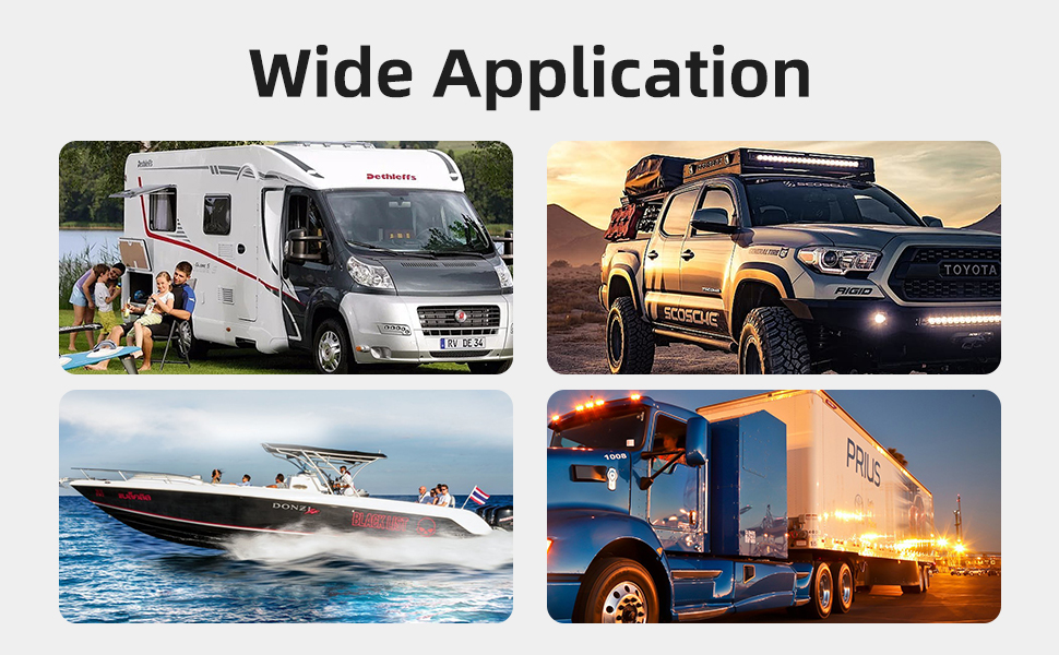
For automotive electricians, RV modifiers, and marine outfitters, installing a reliable dual battery system is one of the most requested services. At the heart of a cost-effective and efficient dual battery setup lies the Voltage Sensitive Relay (VSR), also known as a Smart Battery Isolator.
While the concept is simple, proper installation is critical to ensure vehicle safety and battery longevity. In this comprehensive guide, Daier Electronics provides a professional-grade wiring diagram, a deep dive into the working principles of VSRs, and a comparison with other isolation methods to help you choose the right solution for your clients.
Part 1: Understanding the Technology: How a VSR Works?
Before diving into the wiring, it is essential for installers to understand the internal logic of the Smart Battery Isolator. Unlike old-school mechanical isolators or simple solenoids, a VSR is fully automated and voltage-dependent.
The Intelligent Switching Logic:
The VSR monitors the voltage of the primary (start) battery.
- Cut-In (Combine) Voltage: Once the engine starts and the alternator raises the system voltage to a preset level (typically 13.3 Volts), the VSR engages. This closes the circuit, allowing the alternator to charge both the start battery and the auxiliary battery simultaneously.
- Cut-Out (Isolate) Voltage: When the engine is turned off and the voltage drops below a certain threshold (typically 12.8 Volts), the VSR disengages. This separates the batteries.
Why is this critical?
This logic ensures that accessories like fridges, inverters, and lights connected to the auxiliary battery never drain the start battery. Your client will always have enough power to start their engine, regardless of how much power they used overnight.
Part 2: VSR vs. Diode Isolators vs. DC-DC Chargers
A common question from procurement managers and DIYers alike is: “Why choose a VSR over other methods?” Here is a technical comparison:
1. VSR vs. Diode Isolators (Legacy Tech)
-
The Problem with Diodes: Traditional diode isolators suffer from a significant voltage drop (usually 0.6V to 1.0V). This means the auxiliary battery never receives a 100% full charge from the alternator, leading to reduced battery life (sulfation).
-
The VSR Advantage: Daier’s VSR creates a direct connection with zero voltage drop. The auxiliary battery receives the full charging voltage, ensuring maximum capacity and lifespan.
2. VSR vs. DC-DC Chargers
-
The Cost Factor: DC-DC chargers are excellent for smart alternators or mixing battery types (e.g., Lead-acid charging Lithium), but they are expensive (often 5x-10x the price of a VSR) and complex to install.
-
The VSR Niche: For standard alternators and budget-conscious builds (where both batteries are Lead-Acid or AGM), the VSR is the most cost-effective and reliable solution. It offers the best ROI (Return on Investment) for general off-road and marine applications.
Part 3: The Professional Wiring Diagram
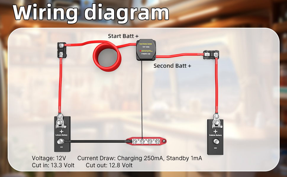
This diagram illustrates a standard negative-ground vehicle setup. Please note the strategic placement of circuit protection devices.
Critical Components Breakdown:
-
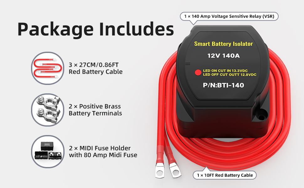
Smart Battery Isolator (Daier Model): Rated for 140A continuous current, IP65 waterproof.
-
Start Battery: The vehicle’s existing battery.
-
Auxiliary Battery: Deep cycle battery (AGM, Gel, or standard Lead-Acid).
-
Circuit Breakers / Fuses: Mandatory for safety. We recommend installing a 100A-150A fuse or circuit breaker on the positive cable near both batteries. This protects the cable from short circuits in case of an accident or insulation failure.
-
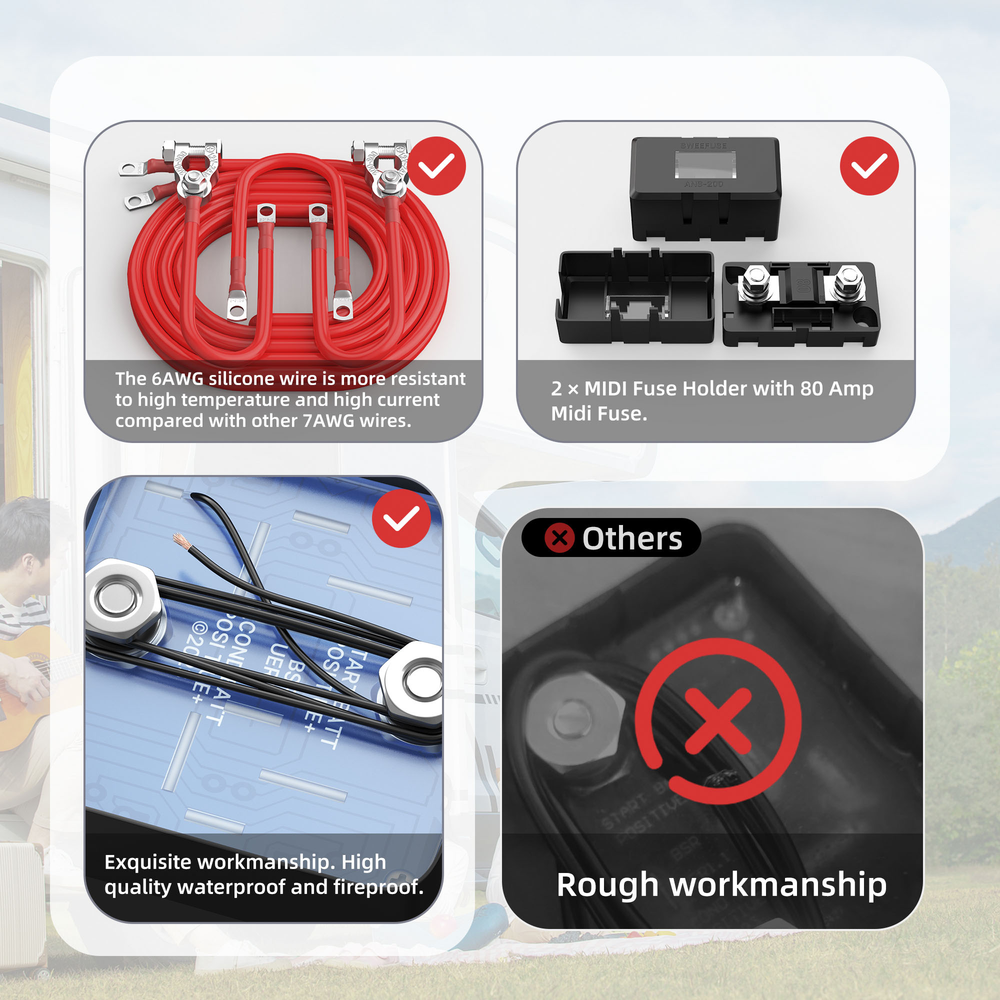
Cables: Use high-quality copper welding cable. For runs under 3 meters, 6 AWG is acceptable. For longer runs (e.g., to a caravan or rear of the truck), upgrade to 4 AWG or 2 AWG to minimize voltage drop.
Part 4: Detailed Step-by-Step Installation Instructions
Follow these professional steps to ensure a safe and durable installation.
Step 1: Location Selection
Mount the VSR firmly. Ideally, it should be in the engine bay, close to the main battery, but away from extreme heat sources like turbochargers or exhaust manifolds. The Daier VSR features a surface-mount or panel-mount option for flexibility.
Step 2: Cable Preparation and Termination
-
Measure your cable lengths carefully.
-
Strip the insulation and use hydraulic crimpers to attach heavy-duty copper lugs.
-
Pro Tip: Always use heat shrink tubing over the lug/cable connection. This prevents moisture ingress and corrosion, which is the #1 cause of failure in marine environments.
Step 3: Making the Connections
-
Disconnect Negatives: Always disconnect the negative terminals of both batteries first.
-
Main Positive: Connect the positive cable from the Start Battery to the VSR terminal marked (usually with a Red Dot).
-
Aux Positive: Connect the positive cable from the Auxiliary Battery to the second VSR terminal.
-
Ground Wire (Crucial Step): The small black wire exiting the VSR is the ground reference. This MUST be connected to a clean chassis ground or the battery negative. Without this, the VSR’s internal electronics cannot sense voltage, and the unit will not operate.
Step 4: The LED Indicator Check
Once wired, reconnect the battery negatives.
-
Start the vehicle.
-
Wait for a few seconds. As the voltage climbs above 13.3V, you should hear a distinct “Click” from the relay.
-
The LED indicator on the VSR should light up (usually Red).
-
Turn off the engine. The LED will stay on for a while (surface charge) and then turn off once the voltage stabilizes below 12.8V.
Part 5: Troubleshooting Common Issues
For our B2B partners, being able to troubleshoot customer issues is vital. Here are common scenarios:
Scenario A: The VSR clicks on and off rapidly (“Chattering”).
-
Cause: Voltage drop in the cables. When the VSR engages, the rush of current to a dead aux battery drops the voltage at the VSR below 12.8V, causing it to cut out.
-
Solution: Charge the auxiliary battery manually first, or upgrade to thicker cables.
Scenario B: The LED never turns on.
-
Cause: Poor ground connection or blown fuse.
-
Solution: Check the small black ground wire. Ensure the fuse on the main power line is intact.
Scenario C: The VSR stays on after the engine is off.
-
Explanation: This is normal. A healthy battery holds a surface charge above 12.8V for some time. Turning on headlights or a load will cause it to disengage faster.
Part 6: Why Sourcing Daier VSRs Benefits Your Business
As a professional distributor or installer, you need products that reduce warranty claims and increase customer satisfaction.
-
Reliability: Our VSRs undergo rigorous life-cycle testing to ensure the relay contacts do not weld or fail under heavy load.
-
Durability: The IP65-rated casing uses UV-stabilized plastic, suitable for harsh Australian outback or marine saltwater conditions.
-
Complete Solutions: Daier doesn’t just sell the VSR. We offer complete Dual Battery Wiring Kits, including pre-crimped cables, fuses, lugs, and the isolator, ready for retail shelves or quick installation.
Conclusion
A dual battery system is an essential upgrade for any adventure vehicle. By using a Daier Smart Battery Isolator, you are ensuring a “install-it-and-forget-it” reliability for your customers.
Looking for a reliable supplier for your auto electrical business?
Contact Daier Today for Wholesale Pricing and Custom OEM Solutions