Marine Switch Selection Guide for Boat DC Systems
- October 21, 2026
- 15
- DAIER Technical Team
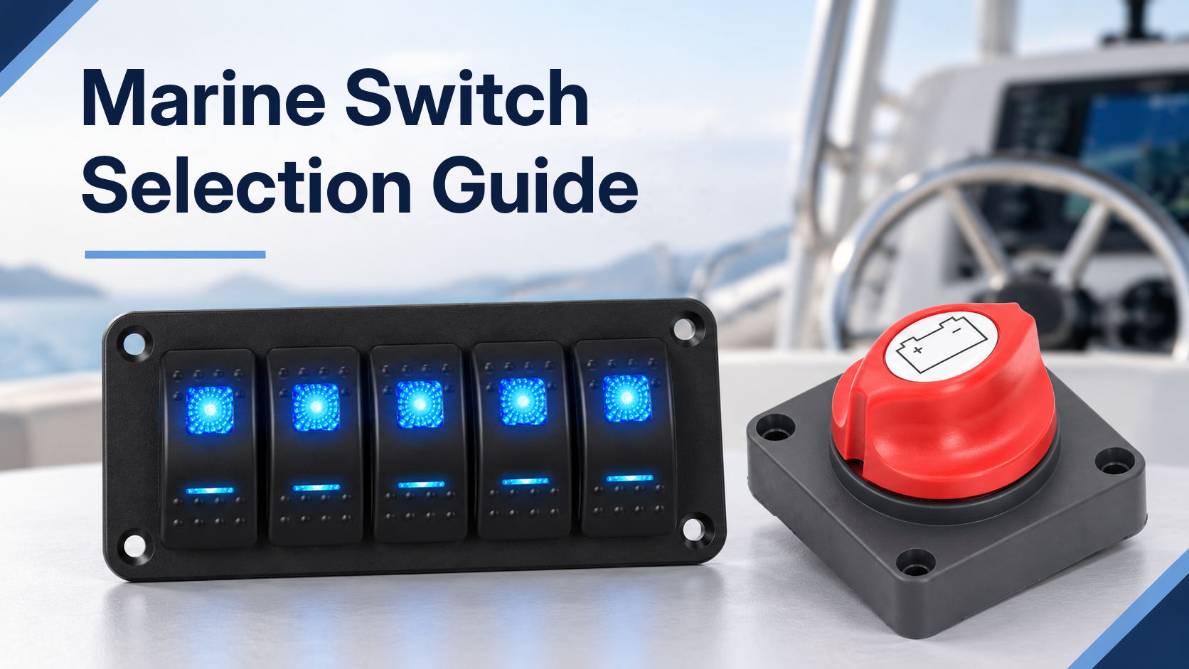
Marine switch selection starts with the circuit and installation location. A boat switch must have the correct DC rating and contact function, fit the panel and wiring, and provide the required protection against exposure. A product described as waterproof or marine is not automatically suitable for every space on a vessel. This guide covers low-voltage DC panel controls, battery switches and pre-wired panels, with examples from the DAIER Marine Switch category.
1. Environmental Requirements for Marine Switches
Corrosion and Connection Quality
Salt and moisture can damage exposed terminals and increase connection resistance. Inspect the specified contact and terminal materials, plating, connector protection and cable support. An IP rating does not establish salt-spray resistance, UV durability or vibration performance. Where those conditions matter, request the relevant test evidence for the exact model. Follow the specified terminal assembly and tightening method; do not assume every switch uses the same materials or can tolerate repeated retightening.
Interpreting IP Ratings
The two digits describe protection against solid objects and water. IP65 and IP66 describe dust-tight enclosures tested against water jets of different severity. IP67 covers temporary immersion under specified test conditions. IP68 covers immersion under conditions specified for the product, rather than unlimited underwater use. An immersion rating alone does not establish compliance with the jet tests. Request the actual test scope and installation conditions.
Check whether the rating applies to the panel face, the complete switch or the assembled panel. Rear terminals, panel cutouts, seals and cable entries may need separate protection. Choose for the actual rain, spray or washdown exposure; a location label such as cockpit or transom does not determine one universal minimum IP rating.
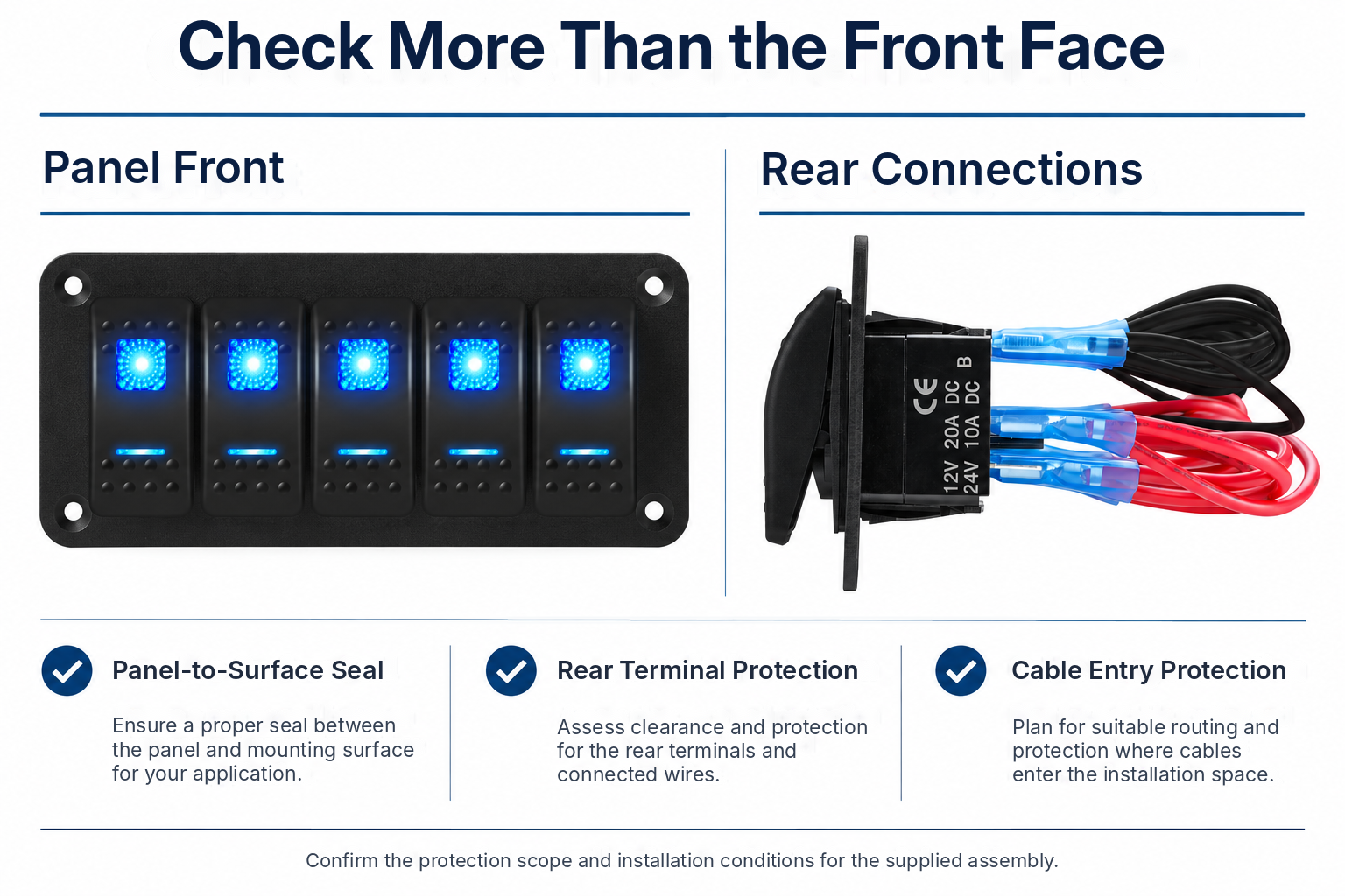 Check the panel-to-surface seal, rear connections and cable entries, and confirm which areas the specified protection rating covers.
Ignition Protection Is a Separate Requirement
Equipment in spaces where flammable vapours may accumulate may require ignition protection under the applicable vessel requirements. IP65 or IP67 does not demonstrate this capability. Request model-specific evidence for the applicable ignition-protection standard, such as ISO 8846, SAE J1171 or UL 1500, where required. Confirm the installation location and documentation with the vessel designer. Do not infer ignition protection from a marine product name, a sealed housing, or a battery-switch current rating.
2. Marine Rocker Switches for Dash Panels
Single LED and Dual LED Controls
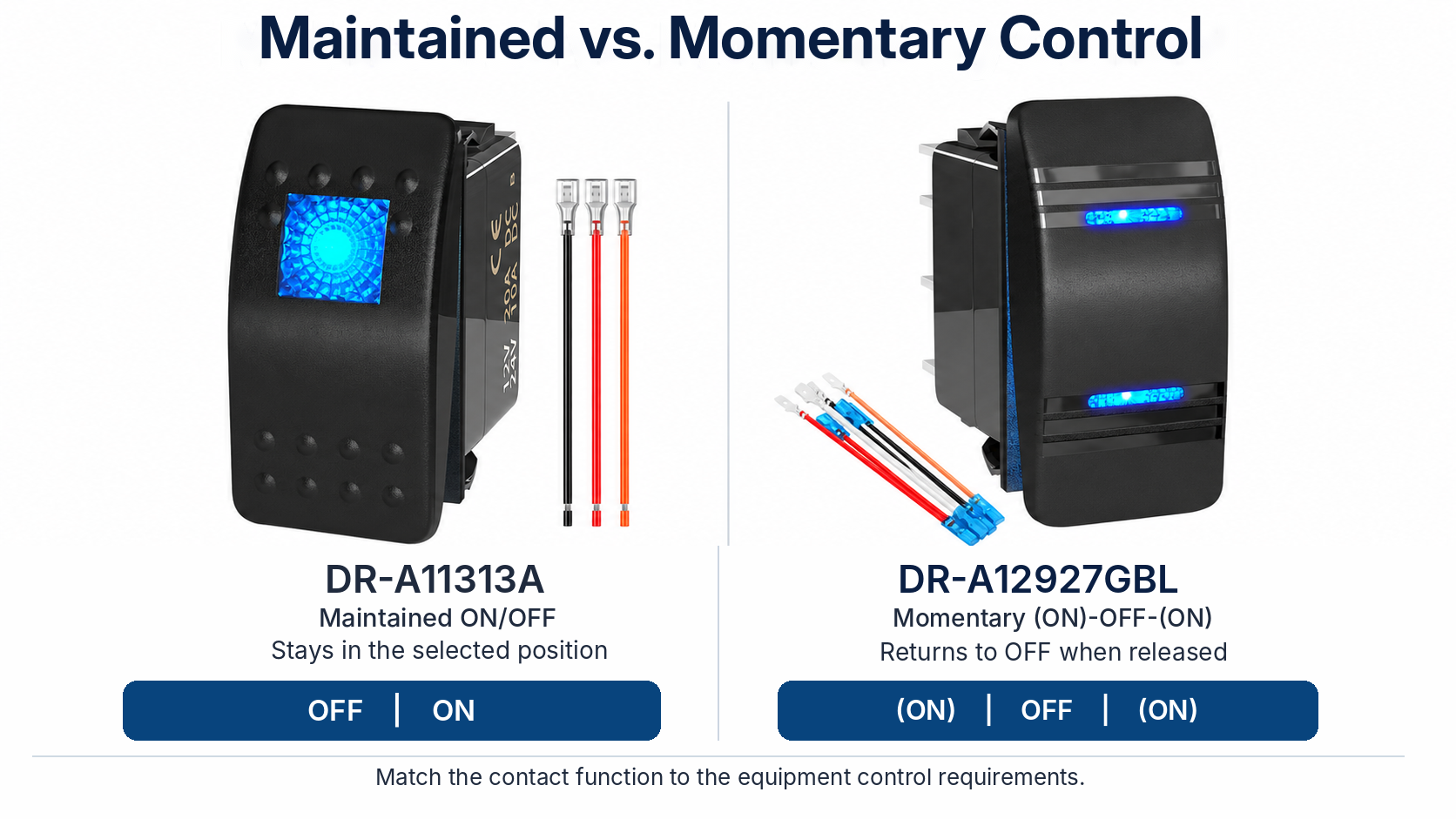
The DR-A11313A is listed as a three-pin SPST ON/OFF rocker with a single LED and a 20A rating at 12V DC. Its LED indicates the switch state when wired as specified; it does not prove that the connected load is operating. Confirm the terminal diagram, cutout and approved protection scope for the supplied variant. Request model-specific IP documentation and confirm which surfaces and connections it covers before specifying an exposed installation.
The DR-A11X25 illustrates a dual-LED arrangement that can provide legend illumination and a separate switch-state light. The catalog lists 20A at 12V DC and an IP67 grade. Illumination behaviour depends on the terminal connections and variant. A lamp described as always on requires a powered illumination connection and may draw standby current. Confirm LED voltage, polarity and the wiring diagram before integrating the switch into a battery-powered panel.
Direct Switching or Relay Control
Check the DC rating for the actual load type. A general current figure does not establish suitability for a motor, lamp inrush or other transient demand. DC and AC ratings are not interchangeable. Where the load exceeds the switch capability, or the equipment requires it, use the panel switch to operate an appropriately rated relay, contactor or controller. Locate and protect the power circuit separately from the control circuit.
Momentary Controls for Equipment Requests
The DR-A12927GBL is listed as a seven-pin DPDT (ON)-OFF-(ON) momentary rocker with dual LEDs, 20A at 12V DC, 10A at 24V DC and IP65. Parentheses indicate positions that return when released. It is a candidate control format for equipment requiring two momentary requests, subject to the equipment diagram and load requirements. Do not assume that seven pins establish a universal motor-reversing wiring pattern or authorize direct switching of a windlass, trim pump or hatch motor. Use the specified control interface and interlocks.
3. Toggle and Push Button Switches
Matching Contact Function to the Circuit
A toggle can provide maintained ON/OFF control, while a momentary push button can provide a horn or start request. Function must follow the equipment requirements: a ventilation blower may need maintained operation, and an automatic bilge pump may need an independent automatic supply and a separate manual control. Do not select momentary operation simply because the load is a pump or blower. A push button can also be latching; confirm its reset behaviour and contact arrangement.
An indicator lamp normally shows the state of its wiring connection, while a voltmeter shows voltage at the point being measured. Neither automatically confirms that a load is running. Where actual operating feedback is required, use the equipment’s specified feedback signal. For toggle and push-button alternatives, compare the relevant Auto Switch models and confirm the DC load rating, cutout, mounting depth and sealing requirements. This DC guide does not establish suitability for shore-power or inverter AC circuits.
4. Marine Battery Disconnect Switches
Continuous and Cranking Ratings
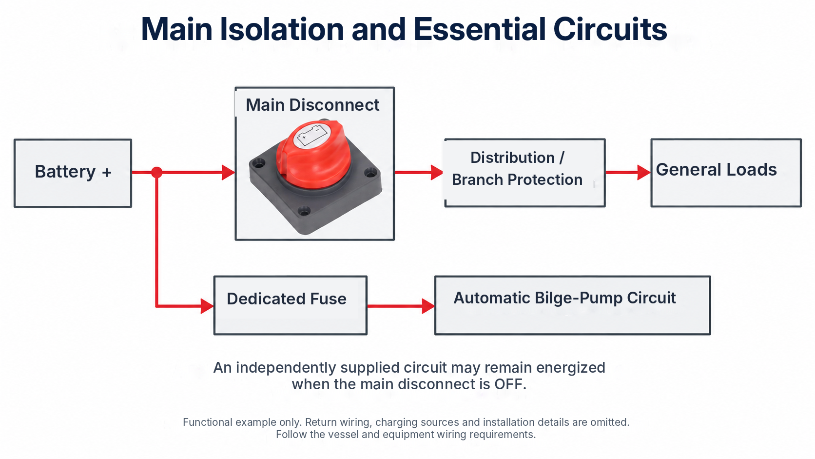
Battery switches have separate continuous, intermittent and cranking ratings. Cranking capacity is a short-duration specification and must be checked with its stated duration and duty conditions. The ASW-A702 page lists 275A continuous at 12V DC, a 1250A cranking figure and a 12V–48V DC application range. Confirm the approved voltage limit, cranking duration, cable and lug arrangement, and installation requirements for the ordered variant. For a space requiring ignition protection, obtain the applicable model-specific test evidence before selecting a battery switch.
Isolation and Circuits That Remain Powered
A disconnect opens its defined battery circuit; it does not provide overcurrent protection or isolate every possible source on the boat. The system diagram must account for other batteries, chargers and charging equipment. Automatic bilge-pump circuits or other designated essential loads may need a separately protected supply that remains available when the main switch is off. Follow the pump and vessel wiring requirements and identify circuits that remain energized before servicing.
Do not turn a battery switch to OFF while the engine or alternator is charging unless the charging system explicitly supports that operation. Interrupting the battery connection can damage charging equipment. A modular interlocking housing only describes mechanical mounting; two interlocked ON/OFF switches do not automatically provide bank selection, battery combining or charging isolation. Those functions require a suitable switch or controller and an approved connection diagram.
5. Selecting a Marine Switch Panel
Pre-Wired Panels and Total Capacity
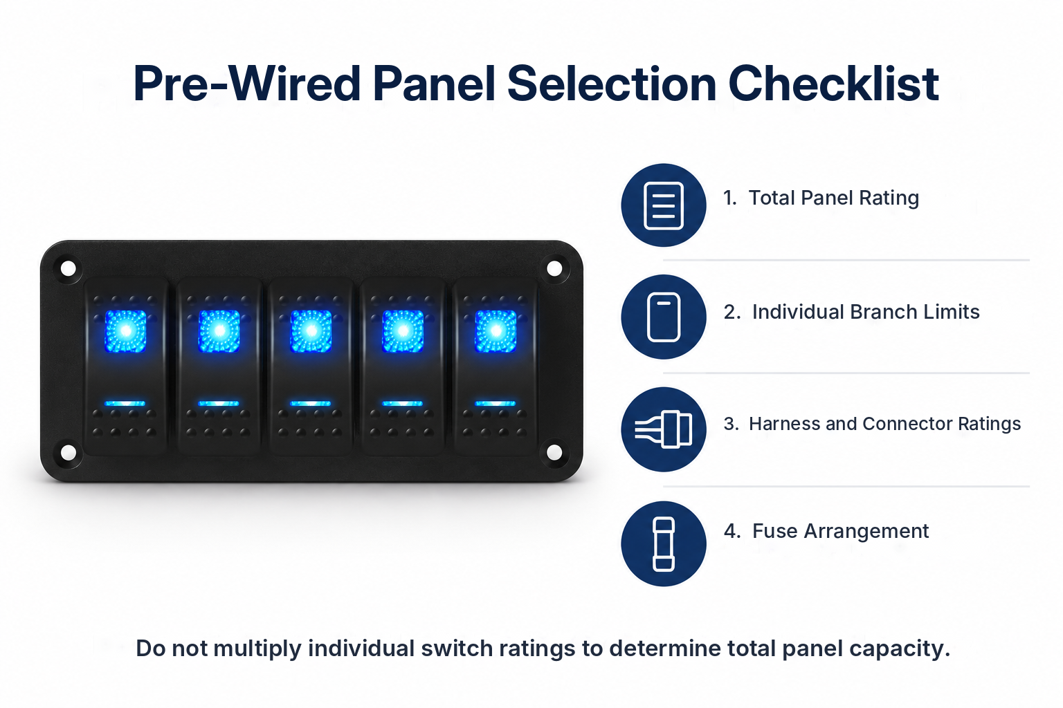
The PN-1815 is a pre-wired five-gang ON/OFF rocker panel with labels and a listed IP65 grade. Its catalog gives 20A at 12V and 10A at 24V, but those figures must not be multiplied by five to establish a panel supply rating. Request the total panel rating, branch limits, harness conductor sizes, connector ratings and fuse arrangement. Pre-wiring simplifies assembly but does not replace project-specific cable sizing, load assessment or installation checks.
Building the Circuit Schedule
List each load, its operating current and starting demand, control function, required protection and expected simultaneous operation. Size the main feed for the design load and installation conditions, including voltage drop. Each branch must have appropriate overcurrent protection for its conductor and equipment. Navigation-light switching must support the required operating modes, and bilge-pump controls must preserve the intended automatic operation. Reserve spare positions only when the feed and distribution layout can support later additions.
Protection and Return Distribution
An unfused busbar provides a common electrical connection; it does not protect the circuits connected to it. Use suitable fuses or circuit breakers and verify their DC voltage and interrupt ratings. Review DAIER Fuse Blocks and Holders for branch-protection hardware, and Busbars and Power Distribution Blocks for common feed or return connections. Check assembly ratings, individual terminal limits and the approved circuit arrangement. Keep positive feeds and negative returns distinct, and follow the vessel’s specified bonding design.
6. Marine Switch Types Compared
| Type | Control function | Checks before selection |
|---|---|---|
| Maintained rocker or toggle | Remains in its selected position | DC load rating and required operating modes |
| Illuminated rocker | Control with legend or state illumination | LED voltage and terminal diagram and standby demand |
| Momentary switch | Request active while held | Controller interface and return action and interlocks |
| Battery disconnect | Isolates a defined battery circuit | Continuous and cranking ratings and live exceptions |
| Pre-wired panel | Groups several branch controls | Total supply and harness and branch-protection limits |
The comparison describes functions, not universal ratings. Current capability, IP protection, terminal diagrams and approvals vary by exact model and installation. A sealed switch may still be unsuitable for the load or location, and a high-current switch may still lack the required environmental or ignition-protection evidence.
7. OEM Selection and Purchasing Details
Start with the Marine Switch category for individual rocker controls. Use Auto Switch for broader switch alternatives, and the Battery Switch and Switch Panel categories for supporting assemblies. For an OEM enquiry, submit the circuit list, maximum operating voltage, continuous and starting loads, required switch function, pole and throw arrangement, LED behaviour, panel cutout and thickness, rear clearance, terminal or harness requirements, exposure conditions, required test documentation and expected order quantity through the contact page. Drawings and a wiring diagram help identify whether a catalog part or a reviewed custom option is appropriate.
