Technical Briefing: Circuit Integrity and Fuse Protection Protocols in Professional 12V Systems
- July 10, 2026
- 458
- DAIER Technical Team
In the engineering of professional automotive, marine, and industrial electrical systems, circuit protection is the primary line of defense against catastrophic failure. A blown fuse is not a localized event; it is a technical data point indicating a breach of safety parameters. For OEMs and fleet managers, understanding fuse forensics and standardized replacement protocols is essential for minimizing MTTR (Mean Time to Repair) and mitigating fire-related liability. This briefing outlines the engineering logic of 12V protection, from amperage color-coding to advanced failure analysis.

1. The Engineering Standard: Amperage Logic and Color Coding (SAE J1284)
Reliability in the field depends on the standardization of components. The automotive industry utilizes the SAE J1284 standard for blade-style fuses to ensure that any technician, regardless of the vehicle’s origin, can identify a circuit’s capacity at a glance. In professional manufacturing, adhering to these color codes is not an aesthetic choice but a mission-critical safety requirement.
The Professional Amperage Matrix:
| Basic Catalog (Amp) | Color Code | Industrial/OEM Application |
| ATC-1 | Black | Micro-sensors, digital logic feeds, ECU memory. |
| ATC-2 | Gray | Precision telemetry sensors, anti-theft logic. |
| ATC-3 | Violet | Low-draw LED status indicators, signal relays. |
| ATC-4 | Pink | Instrument cluster illumination, CAN-bus signals. |
| ATC-5 | Tan | Control modules, mirror actuators, dash displays. |
| ATC-7½ | Brown | Interior lighting, low-power cabin electronics. |
| ATC-10 | Red | Fleet Standard: Infotainment, standard USB hubs, telemetry. |
| ATC-15 | Blue | Fuel pumps, wiper motors, auxiliary light arrays. |
| ATC-20 | Yellow | High-draw outlets, headlights, cooling fans. |
| ATC-25 | Clear | Power windows, HVAC actuators, seat adjustment motors. |
| ATC-30 | Green | Heavy Duty: High-output HVAC, audio amplifiers, hydraulics. |
| ATC-40 | Orange | Primary Protection: Main battery feeds, radiator fans. |
Technical Insight: The metal “bridge” within the fuse is calibrated to melt at a specific temperature. Installing an incorrect amperage (e.g., substituting a 10A Red with a 20A Yellow) shifts the “weakest link” from the sacrificial fuse to the wire insulation itself. In a professional build, this creates a significant risk of thermal runaway and subsequent vehicle fire.
2. Failure Forensics: Overload vs. Short Circuit
A professional technician must be able to perform a “visual autopsy” on a failed fuse to determine the root cause of the electrical fault. Replacing a fuse without identifying the failure mode is a reactive approach that leads to recurring downtime.
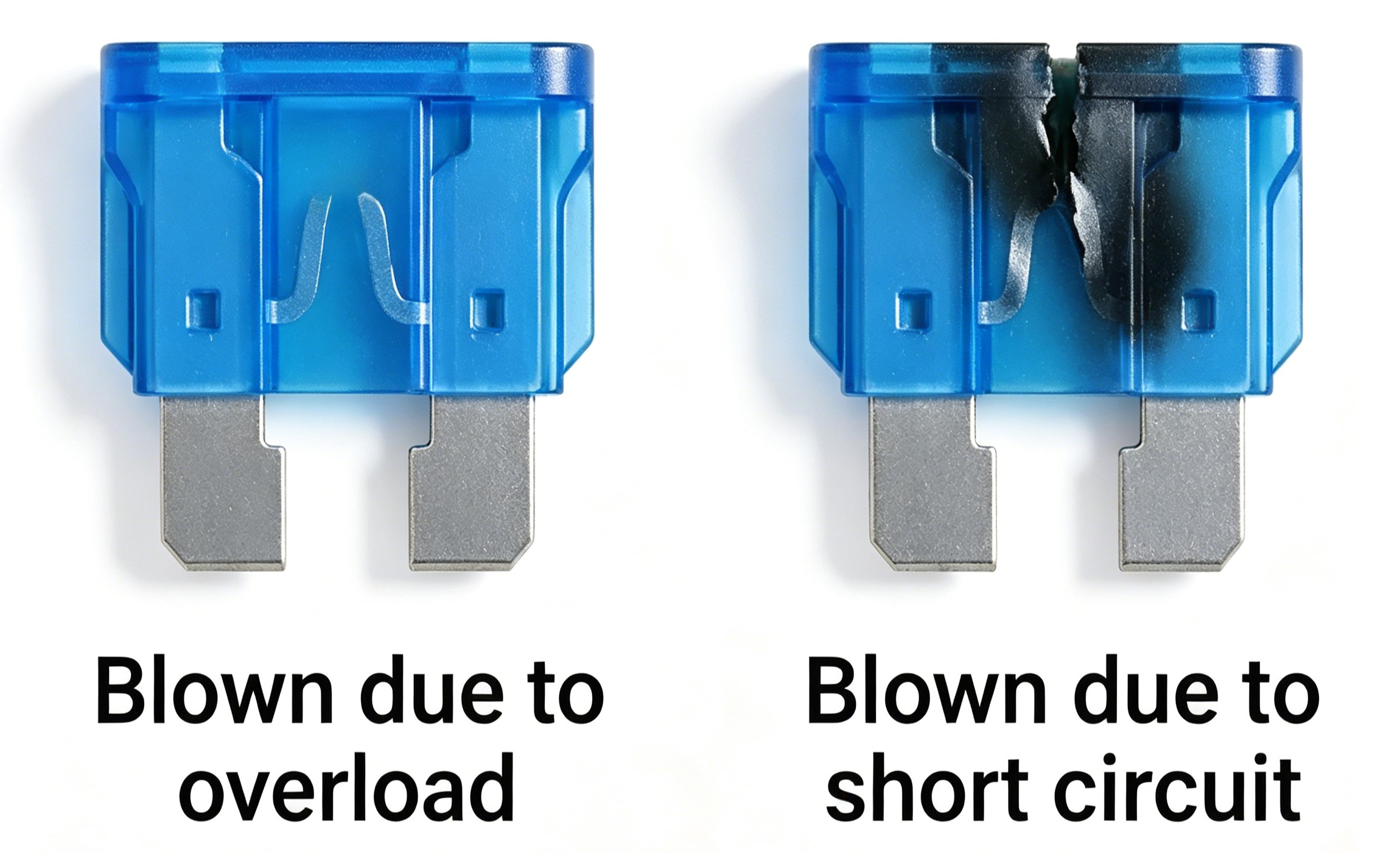
Figure 1: Forensic analysis of failed fuses. A clean break (left) indicates thermal overload; a charred interior (right) indicates a catastrophic short circuit.
- Thermal Overload (The “Clean Break”):
If the metal bridge is melted but the plastic housing remains clear, the circuit has experienced a sustained draw slightly above its rating. This is typical when an OEM circuit is taxed by additional aftermarket accessories or when a motor is beginning to seize, increasing its current draw.
- Short Circuit (The “Catastrophic Arc”):
Charring, black soot, or metal splatter inside the fuse indicates an instantaneous surge of hundreds of amps. This signifies a Direct Short to Ground, where the positive conductor has bypassed the load and contacted the chassis. In professional fleet maintenance, this fuse must never be replaced until the wiring loom has been inspected for physical damage.
3. Form Factors: Sizing Standards for High-Density Integration
OEMs must choose fuse form factors based on space constraints and current density requirements. While the electrical logic remains the same, the mechanical footprint varies across professional platforms.
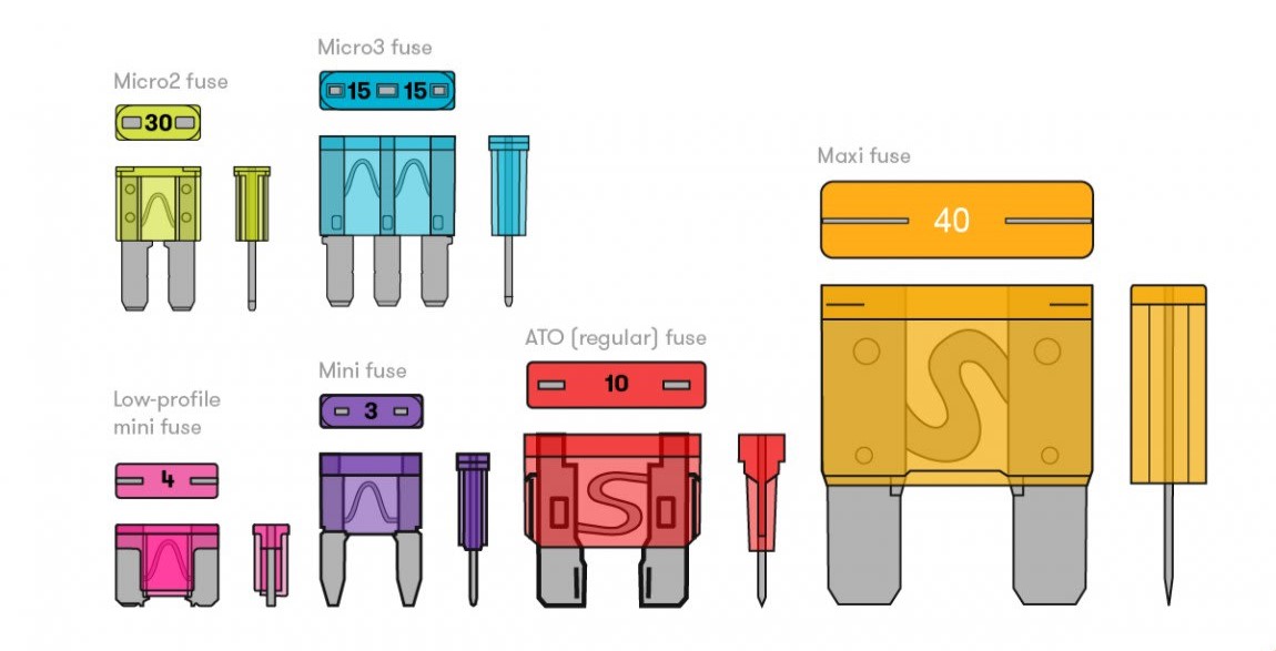
Figure 2: Form factor selection is critical for high-density power distribution modules.
- Micro/Mini Fuses: The standard for modern, space-constrained vehicle dashboards. They allow for high-density integration in complex Power Distribution Centers (PDCs).
- ATO/ATC (Regular): The most robust and widely used standard for marine and off-road aftermarket builds. Their larger surface area provides better heat dissipation in high-vibration environments.
- Maxi Fuses: Reserved for high-current “Master” lines. These protect the main feed from the battery to the distribution hub.
4. Standardized Diagnostic Protocols: Minimizing MTTR
Efficiency in a professional workshop is measured by MTTR (Mean Time to Repair). Technicians should utilize a systematic protocol to ensure safety and accuracy.
- Continuity Verification: Never rely on visual inspection alone. Professional diagnostics require a Digital Multimeter (DMM).
-
- Set the DMM to the Continuity (Audible) setting.
-
- Touch the test points on the back of the fuse while it is still seated in the Fuse Block.
-
- Silence indicates an open loop (failed fuse).
- Isolated Extraction: Utilize a non-conductive, plastic Fuse Puller.
-
- Prohibited Practice: The use of needle-nose pliers or metal tools is strictly prohibited in professional settings. Metal tools can cause secondary arcing between terminals, potentially damaging sensitive ECU components or the fuse block housing itself.
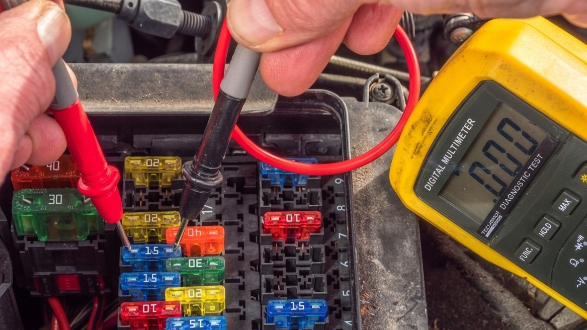
Figure 3: Professional continuity testing using a Digital Multimeter (DMM) to ensure 100% accuracy in fault detection.
5. Risk Management: The Hazard of Improper Sizing
The “Golden Rule” of electrical engineering: The fuse protects the wire, not the device.
A 15A fuse is selected because the wire gauge in that circuit is rated to carry 20A safely. If a technician “sizes up” to a 30A fuse to stop a nuisance blow, they have effectively converted the wire into a heating element. Under a fault condition, the wire insulation will melt long before the fuse pops, leading to catastrophic fire.
OEM Best Practice: If a circuit is experiencing frequent failures, the solution is to re-engineer the load distribution or upgrade the wire gauge, never to increase the fuse amperage beyond the original design specification.
6. Environmental Resilience and Preventive Maintenance
In marine and heavy industrial sectors, environmental stressors significantly impact fuse longevity.
- Oxidation Management: In salt-air environments, the legs of the fuse can develop a layer of oxidation. This increases contact resistance, generating localized heat that can cause a “nuisance blow” even at normal current levels.
- Vibration Mitigation: High-vibration environments (corrugated roads or heavy seas) can cause fuses to vibrate loose in their sockets. This creates micro-arcs that pit the metal contacts of the Fuse Holder, eventually leading to a complete circuit failure.
Recommendation: Professional builds should utilize Waterproof Inline Fuse Holders with IP67 ratings for any exterior or engine-bay mounted circuits.
Conclusion: Partnership in Reliability
Fuses are the silent sentinels of any 12V architecture. For the professional builder, success is found in the details—standardized color-coding, high-conductivity materials, and disciplined diagnostic protocols. By ensuring that every circuit is correctly fused and protected, you protect your brand’s reputation and your client’s safety.
At Daier, we provide the industrial-grade components required for these high-standard systems. From our LED-Indicated Fuse Blocks to our Manual Reset Circuit Breakers, every part is engineered to meet the demands of professional field use.
Strategic Procurement: For wholesale technical specifications, custom OEM branding, or engineering data sheets, contact the Daier technical sales team today.
