The Ultimate Guide to Wiring a 4-Pin & 5-Pin Relay
- November 5, 2025
- 10,505
- DAIER Technical Team
An automotive relay lets a low-current switch control a separate, higher-current circuit for a light bar, fan or horn. This guide compares a common 4-pin normally open relay with a 5-pin changeover relay and explains how to wire and protect a typical 12V accessory circuit.
What is a Relay and Why Do You Need One?
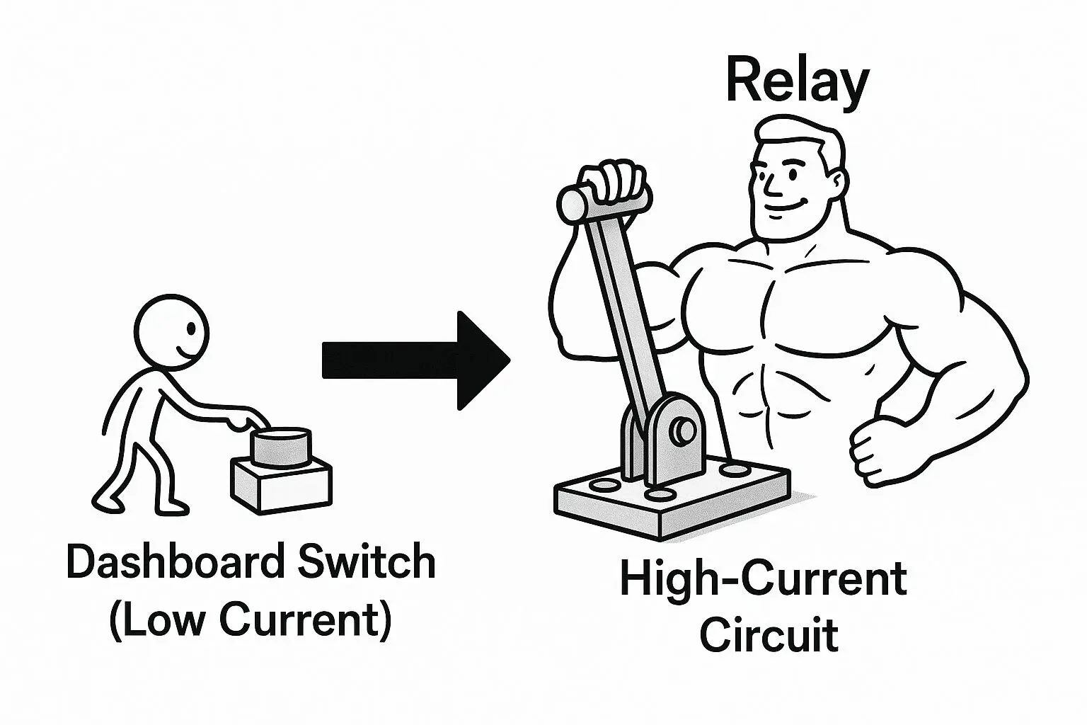
A relay is an electrically operated switch. The dashboard switch controls the relay coil, while the relay contacts carry the accessory current through a separate fused feed. This keeps the accessory load off the dashboard switch and its control wiring.
The Core Principle: How Does a Relay Actually Work?
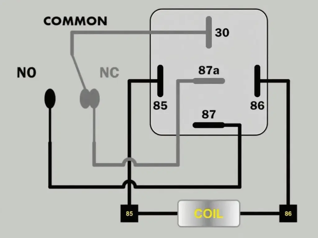
An automotive relay has two circuits. The coil circuit uses pins 85 and 86. The load circuit uses the common contact at pin 30 and the switched contacts.
- When the coil is energized, pin 30 connects to the normally open contact at pin 87.
- When the coil is de-energized, pin 30 disconnects from pin 87. On a changeover relay, pin 30 then connects to the normally closed contact at pin 87a.
The Ultimate Wiring Guide: 4-Pin vs. 5-Pin Relays
This example uses pin 87 of a 5-pin changeover relay to switch one accessory. The same connections apply to the common 4-pin normally open relay. Verify the diagram on the housing before connecting the socket.
Load circuit
Battery + → fuse near battery → pin 30
Pin 87 → accessory +
Accessory − → ground
Coil circuit
Fused +12V control supply → switch → pin 86
Pin 85 → ground
4 Pin vs 5 Pin Relay, Side by Side
| Pin | Function | 4-pin NO | 5-pin SPDT |
|---|---|---|---|
| 30 | Common contact. Fused feed in this example. | Yes | Yes |
| 85 | Coil ground in this example. | Yes | Yes |
| 86 | Switched positive coil feed in this example. | Yes | Yes |
| 87 | Connects to 30 when the coil is energized (NO). | Yes | Yes |
| 87a | Connects to 30 when the coil is de-energized (NC). | No | Yes |
Check the diagram on the relay housing. A 5-pin changeover relay (SPDT) has an 87a contact. A dual-87 relay has two normally open outputs. If you use a changeover relay to switch a single accessory on and off, use pin 87 and insulate any unused 87a wire in the socket.
What About a 4-Pin Relay?
The common 4-pin normally open relay (SPST-NO) uses 30, 85, 86 and 87. Check the relay diagram and socket pin positions before wiring or substituting either type.
Where to Add the Fuse
For a battery-fed accessory, put the fuse in the positive feed as close to the battery as practical. Use an inline holder for a single branch. If a main feed supplies several branches, protect the main feed near the source and fuse each branch at the distribution point as required by its wire and load.
A fuse block keeps branch fuses in one place. For wet locations, choose a fuse block with suitable ingress protection for the mounting location.
Rating and Coil Suppression
Select the coil voltage for the control circuit and check the contact rating for the DC system voltage and actual load type. A 30A or 40A resistive rating alone does not establish suitability for a motor or lighting load. Check both running current and startup or inrush current against the manufacturer’s ratings. For a changeover relay, check the NO and NC ratings separately.
Follow the polarity printed on a relay with an internal suppression diode. In a common positive-trigger arrangement, 86 is positive and 85 is ground. Reversing the marked polarity can forward-bias the diode and damage the driver, diode or circuit protection.
If an ECU, body control module or timer drives the coil, check its output type and suppression requirements before connecting it. Use a relay and suppression method approved for that driver. Diode and resistor suppression have different clamp behavior and can change how quickly the relay releases.
Troubleshooting Common Issues
Symptom 1: The relay “clicks” but the accessory doesn’t turn on.
Possible Cause: The coil is moving the relay. Check for power at pin 30, switched output at pin 87, and a sound ground at the accessory.
Symptom 2: The accessory is always on and won’t turn off.
Possible Cause: Check whether the accessory is connected to 87a. If it is connected to 87, check whether the coil stays energized or the contacts are stuck closed.
Symptom 3: The relay gets very hot.
Possible Cause: Switch off and isolate power. Check the relay’s load rating, the wire size, and the socket and crimp terminals for looseness, corrosion or heat damage before restoring power.
Common Applications for Automotive Relays
Now that you’re a wiring expert, where can you put your new skills to use? Automotive relays are the gateway to countless high-performance upgrades. Here are some of the most popular projects where a relay is not just recommended, but essential:
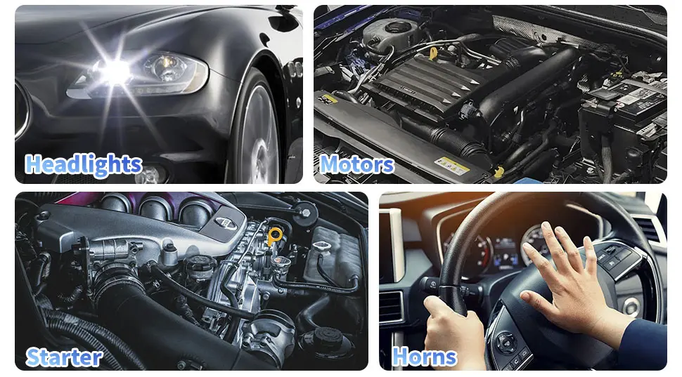
- High-Power Lighting: This is the most common use. Relays are perfect for installing off-road LED light bars and pod lights, powerful fog lights, and upgraded headlight harnesses.
- Electric Cooling Fans: An electric radiator fan draws a significant amount of current when it kicks on. A relay ensures it gets the clean, high-amperage power it needs without overloading your vehicle’s stock wiring.
- Loud Horns: Use a dedicated fused relay circuit when required by the horn manufacturer or when the load exceeds the capacity of the original circuit.
- High-Performance Fuel Pumps: In performance vehicles, upgrading to a high-flow fuel pump is common. A dedicated relay circuit ensures the pump receives consistent voltage for optimal engine performance.
- Audio Systems: A relay can switch an amplifier’s remote turn-on signal or control several audio accessories. Follow the amplifier manufacturer’s requirements for the main power feed.
No matter the application, using a high-quality relay is the key to a safe, reliable, and professional-grade installation.
Relay + Fuse: How to Power Multiple Accessories Safely
A combined relay and fuse box can simplify a build with several independently switched accessories, such as a light bar, air compressor and auxiliary fan.
A fuse relay box combines the relays and the fuses in one enclosure: each accessory gets its own relay slot and its own blade fuse, the main feed enters through a single stud, and every output is labelled. The RB-R6F6-W1, for example, holds six ATC/ATO fuses and five Bosch-style relays plus one RTT7121 relay, and it is built for car, truck, marine and motorsport installations.
If you would rather not crimp every terminal yourself, a pre-wired relay box arrives with the loom terminated and the outputs marked. The RB-R10F10-W1 takes ten ATC/ATO fuses and ten relays (eight 4-pin and two 5-pin), which is enough for a full accessory panel on a truck or a boat.
Not sure how many ways your build needs? Our guide to how to choose a 12V fuse relay box breaks the options down from 4-way to 16-way, and the fuse blocks and holders range covers the ATC, ATO, mini and ANL styles used in most vehicles.
Frequently Asked Questions – FAQ
▸ Do I really need a fuse for my relay?
Yes. In a battery-fed accessory circuit, the fuse protects the feed wire from overheating during a short or overload. Install it as close to the power source as practical.
▸ Can I use a fuse block instead of an inline fuse?
Yes. A fuse block can protect multiple branches. If it is fed by a separate main cable, provide suitable protection for that cable near the power source.
▸ What size fuse should I use for a 12V relay circuit?
Follow the equipment manufacturer’s fuse recommendation and check it against the ampacity of the wiring it protects. Consider both the operating current and startup current. The fuse rating must not exceed the ampacity of the smallest conductor it protects.
▸ Do I need a relay box for multiple accessories?
A relay box is useful when several accessories need independent switching and branch protection. It groups relays and fuses in one serviceable location.
▸ Can I use a 5-pin relay to replace a 4-pin relay?
A 5-pin changeover relay can replace a 4-pin normally open relay if the socket accommodates it and the terminal positions, coil voltage, load ratings and suppression requirements match. Use pin 87 for the load and leave pin 87a unconnected. Insulate any unused 87a wire in the socket.
▸ What wire gauge should I use for my relay wiring?
For automotive wiring, use a wire-sizing chart that accounts for load current, round-trip length, allowable voltage drop and installation conditions such as ambient temperature and bundling. Match the fuse to the wire’s ampacity.
▸ Where is the best place to mount a relay?
Mount the relay in a dry location, away from extreme engine heat and direct water spray, such as on the firewall inside the engine bay or under the dashboard. Mounting it with the terminals facing down can help prevent water from collecting inside.
▸ What is the difference between a 4 pin and a 5 pin relay?
A common 4-pin normally open relay switches pin 30 to pin 87. A 5-pin changeover relay adds the normally closed contact at 87a. A dual-87 relay also has five pins, but both outputs are normally open. Check the housing diagram before connecting the socket.
▸ What is pin 87a for?
Pin 87a is the normally closed contact of a changeover relay. It connects to pin 30 when the coil is de-energized and opens when the coil is energized.
▸ Which pins are the coil on a relay?
Pins 85 and 86 are the coil terminals. In the positive-trigger example, 86 is positive and 85 is ground. For a diode-suppressed relay, follow the polarity marked on its housing or datasheet.
▸ How many amps can a 4 pin relay handle?
The rating depends on the model, system voltage and load type. A 30A or 40A resistive rating does not establish the relay’s rating for a motor or lighting load. Check the datasheet for the applicable switching rating and allowable inrush.
Choose Reliability, Choose Daier
A reliable relay is the heart of a safe and durable custom electrical project. A low-quality relay can fail under load, leaving you stranded or, worse, causing electrical damage.
At Daiertek, we provide a wide range of rigorously tested, high-quality automotive relays designed to handle demanding applications with stability and safety.
